


RECONDITIONING BRAKE ROTORS
After the following instructions are read and understood,
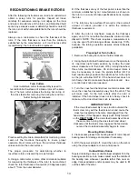
obtain a scrap rotor for practice. Inspect all rotors
carefully for excessive scoring, rust ridges (at the inner
and outer circumference of the rotor), and blemished hard
spots. Any excessive wear or deformity should be noted. If
the rotor is not within acceptable limits, the rotor should be
replaced.
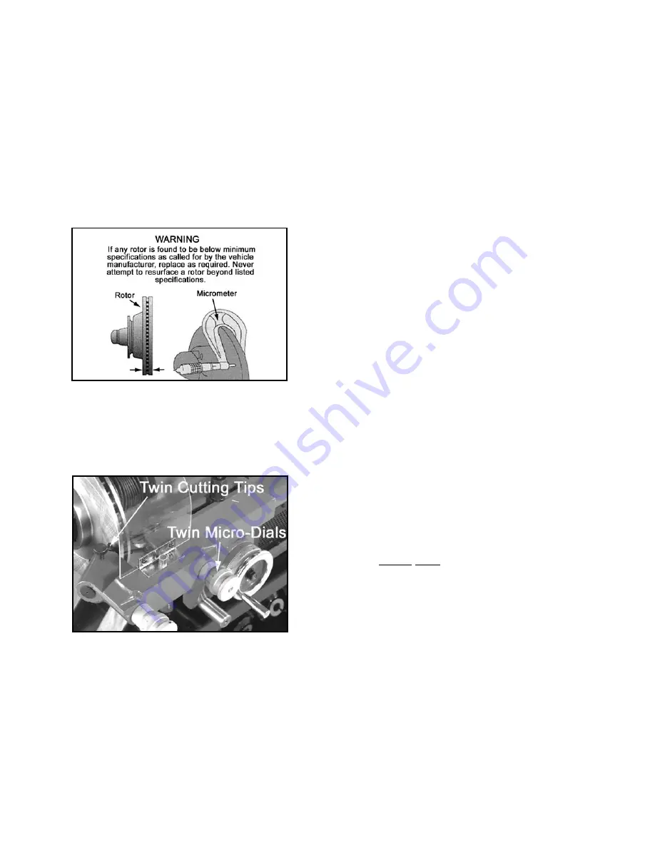
Always use a micrometer to check the thickness of the
rotor. If the rotor thickness is less than the minimum
established by the manufacturer, or if it will be less after
reconditioning, the rotor should be replaced.
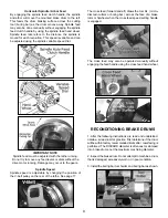
Twin Cutters
A micro-dial twin cutter tool assembly is used to
recondition both surfaces of a brake rotor at the same
time. The twin cutter replaces the boring bar on top of
the cross feed after removing the boring bar and tool
holder boring bar brackets.
Practice setting the micro-dial cutters for machining rotors.
Learn all the functions thoroughly to insure proper
operation. Most rotors will have the minimum thickness
values cast into the outer surface.
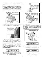
The proper procedure for determining whether to
resurface rotors or discard them is as follows:
A. Using a micrometer or some other micrometer suitable
for measuring the thickness of the rotor to be machined,
check the rotor thickness at four points (90 degrees apart)
about 1" from the outer diameter.
B. If the thickness at any of the four points is less than the
minimum established by car manufacturers as shown on
the rotor or in a current brake specifications book, replace
the rotor.
C. The rotor may be resurfaced if scored or it has a small
amount of runout, provided it is within the minimum
thickness requirement.
D. After the rotor is machined, measure the thickness
again, and, if it is not within the allowable minimum limits,
discard it. NOTE: This check requires a measurement in
only one spot if both braking surfaces cleaned up 100%,
because the turning operation assures almost absolute
parallelism.
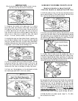
Preparing For Twin Cutters
1. Remove the boring bar and tool holder brackets.
2. Using the spindle feed hand wheel, move the spindle to
its innermost (right hand) position by turning the hand
wheel clockwise and then back off by turning dial wheel
three turns counterclockwise. On some deeper rotors it
may be necessary to move the spindle farther left. For
best results, always position the spindle as far to the right
as the job will allow. NOTE: If the hand wheel does not
turn freely, check to make sure the spindle lock and trav-
el control lock knobs are loosened.
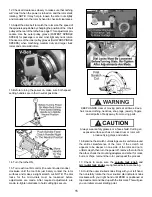
3. Turn the cross feed hand wheel counterclockwise and
move the cross feed assembly away from the arbor. This
will make room for the twin cutters after the rotor is
installed. If the hand wheel does not turn freely, check to
make sure the cross feed lock knob is loosened.
IMPORTANT NOTE
If the cross feed assembly moves too far outward the
feed screw may exit the feed screw nut and cause the
cross feed assembly to become disengaged from the
hand wheel. If this happens, simply push firmly forward
on the
RIGHT SIDE
of the cross feed assembly while at
the same time turning the cross feed hand wheel
clockwise until the feed screw engages the feed screw
nut and the cross feed assembly begins to move.
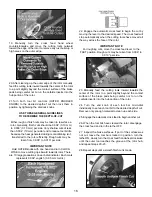
Mounting Brake Rotors
4. Clean excess grease from bearing races of rotor. Inspect
bearing races for damage and replace if necessary.
5. With the power turned off, mount the rotor on the arbor
using the proper adapters, cones, and spacers.
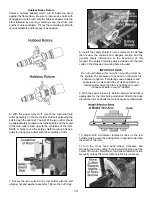
Hubbed Brake Rotors
Tapered centering cones or double taper adapters fit in the
bearing seats. Be sure to make contact near the middle of
the bearing race whenever possible rather than near an
edge. Various adapters and/or spacers may be used to fill
out the shaft of the arbor.
13


