PG
18
PG
18
PG
19
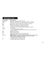
Wire Reference Table
Possible Wires
What They Control
R or V or VR
RH
and
RC
Single power for HEAT and COOL
RH or 4
RH
Power for HEAT (RH not connected to RC with switch in UP position)
RC
RC
Power for COOL (RH not connected to RC with switch in UP position)
W
W
Heat control - Normal 1st stage heat or heat pump aux 1st stage
W2
W2
Normal 2nd stage heat or heat pump aux 2nd stage
W3
W3
Normal 3rd stage heat or heat pump aux 3rd stage
Y
Y
COOL control or 1st stage compression for heat pump
Y2
Y2
2nd stage COOL control or 2nd stage compression for a heat pump
G or F
G
FAN control
C or X
C
24VAC power (to power thermostat)
NOTE: TRANE, AMERICAN STANDARD and YORK often use the letter B for C
H
H
External Humidifier
DH
DH
External De-Humidifier
EX
EX
external fresh air baffle
B
B
Heat pump changeover (cool to heat, powered in heat)
O
O
Heat pump changeover (heat to cool, powered in cool)
B and O
IMPORTANT: If you have a heat pump with both B and O wires (Trane pump
products) DO NOT CONNECT B to B terminal, connect B to C terminal.
Other Trane products use B letter for C wire.
E
n/a Emergency heat (do not connect, tape off)
L
n/a System monitor (do not connect, tape off)
T
n/a Outdoor sensor (do not connect, tape off)


