R-sensors LLC
Bldg. 1, 4, Likhachevsky proezd, Dolgoprudny, 141701, Russia
+7 (498) 744-69-95,
NDAS-N. User Manual.
82
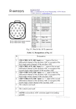
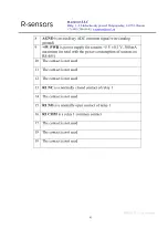
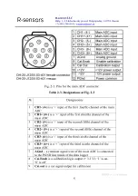
Fig. 2-3. Pins for the main ADC connector
Table 2-3. Designations at Fig. 2-3
№
Designations
1
CH1- (4-)
is a ‘-’ input of the first (fourth) channel of the main
ADC
2
CH1+ (4+)
is a ‘+’ input of the first (fourth) channel of the
main ADC
3
CH2- (5-)
is a ‘-’ input of the second (fifth) channel of the
main ADC
4
CH2+ (5+)
is a ‘+’ input of the second (fifth) channel of the
main ADC
5
CH3- (6-)
is a ‘-’ input of the third (sixth) channel of the
main ADC
6
CH3+ (6+)
is a ‘+’ input of the third (sixth) channel of the
main ADC
7
AGnd
– a common signal wire of the main ADC is connected
to the PGND line inside of the data logger
8
Cal.Enab
is a calibration logic output (+ 3.3 V): ‘1’ is on,
‘0’ is off
9
Cal.out
is a test signal output for calibration

