background image

QR-25 Series 

Quincy Compressor

52201-107, December 2012 

17 

3501 Wismann Lane, Quincy IL - 62305-3116

Pix 1160

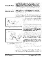
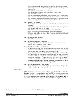
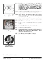
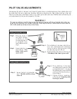
Fig. 3-4  Checking Pressure Relief Valves

& Relieving System Pressure

Pix 1224

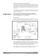
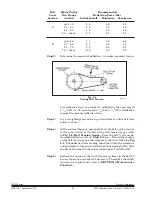
Fig. 3-3  Internal Drain Tube

30 PSIG

Follow ASME code for air receiver tanks and other pressure con-

taining vessels. Pressure vessels may not be modified, welded, 

repaired, reworked or subjected to operating conditions outside 

the nameplate ratings. Such actions will negate code status, affect 

insurance status and may cause property damage, severe injury or 

even death.

Always replace worn, cracked or damaged receivers. Do not use 

plastic pipe (PVC) anywhere in a compressed air system. Serious 

injury or death could result. 

A drain valve must be located in the bottom of the air receiver to allow for 

moisture drainage. Extend piping away from the unit to provide safe and con­

venient removal of excess moisture. An auto matic drain valve is recommended.

If the air receiver is going to be subject to tempera­

tures of 32°F or below, provisions must be made to guard 

against freezing of the pressure relief valves, pressure 

gauge, moisture drain and any moisture in the tank.

Condensation
Rust  can  form  inside  the  crankcase  and  on  internal 

com ponents  as  a  result  of  condensation.  A  compres­

sor  must  operate  long  enough  during  each  run  cycle 

to reach full operating temperature in order to reduce 

the risk of condensation. Lubricant that appears milky 

may have mixed with condensate. Failure to replace 

contaminated lubricant will result in damage to 

the compressor and may void warranty. 

Condensation can also form in the air tank of your 

com pressor. When this happens, a mixture of air and 

mois ture  will  be  expelled  through  the  service  valve 

and  into  what ever  is  connected  to  the  valve  (e.g.  air 

hoses, metal air lines, pneumatic tools, spray guns). An 

in­line filter or dryer, available from your local Quincy 

distributor, may be re quired to eliminate the moisture.

Condensation in the air tank can be kept to a mini­

mum by draining the tank on a daily basis. This also 

reduces the risk of rust developing and weak ening the 

tank.

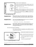
Manual Tank Drain Valve Operation
The manual tank drain valve on portable compressors 

and some stationary compressors is located on the underside of the air tank. 

Portable compressors can be tilted in the direction of the drain to allow re­

moval of tank moisture.

 Some tanks use an internal drain tube (Refer to Fig. 3-3, Internal Drain 

Tube) to drain the moisture. Tank pressure is required to force moisture out 

of the tank through the drain tube. Safe removal of tank moisture from the 

WARNING !

WARNING !

Summary of Contents for QR-25 210

Page 1: ...n its entirety and understood prior to installation by all personnel who install operate and or maintain this product Product warranty information is available at www quincycompressor com about warran...

Page 2: ...y Requirements 10 Mounting 10 System Components 11 Wiring Schematics 12 Induction System 14 Compressed Air Discharge System 15 SECTION 4 START UP OPERATION Pre Starting Checklist 20 Initial Starting O...

Page 3: ...truc tionssupplied by manufacturers of supporting equipment should be read and understood prior to starting the compressor If there are any questions regarding any part of the instructions please call...

Page 4: ...t installing a pressure relief valve of proper size and design between the shutoff valve and the compressor Do not use plastic pipe rubber hose or lead tin soldered joints in any part of the compresse...

Page 5: ...y warned that failure to ob serve the safety precau tions and procedures outlined in this manual may result in serious personal injury damage to property and may void your warranty Quincy Compressor m...

Page 6: ...d in the cylinder The air is then compressed in the cylinder during the upstroke of the piston Total compression from atmo spheric pressure to the final discharge pressure is accomplished in one strok...

Page 7: ...eam air piping Compressed air dryers reduce the moisture vapor concentration and prevent water formation in compressed air lines Dryers are a recommended companion to filters aftercoolers and automati...

Page 8: ...e compressor must start more than six 6 times per hour If the demand for compressed air is continuous and exceeds one half or more of the compressor s capacity Control Version S should be used Once th...

Page 9: ...s run control In either situation the hydraulic unloader protects the compressor from excessive damage caused by a drop in oil pressure Specifications Bore s RPM Maximum Model Stroke LP HP Range PSIG...

Page 10: ...motor Do not substi tute with a triple voltage 208 230 460 3 phase motor Step 5 Read the pressure relief valve nameplate to be sure it does not exceed the working pressure shown on the compressor or a...

Page 11: ...ately ventilated and not closer than 24 inches to a wall or another compressor Note A gas engine will produce carbon monoxide always provide adequate ventilation Inspec tion and mainte nance checks ar...

Page 12: ...d disconnect switch should be provided When a 3 phase motor is used to drive a compres sor any unreasonable voltage imbalance between the legs must be eliminated and any low voltage corrected to preve...

Page 13: ...re The customer is responsible for pro viding a suitable foundation isolator mounting where necessary Mounting Mobile Units Units mounted to truck beds should be fas tened in such a way so as not to c...

Page 14: ...UTION Verify all wires are secure and fasteners are torqued before connecting power to the unit All wires are red unless otherwise specified Dashed lines represent wires supplied by others At Installa...

Page 15: ...AUTION Verify all wires are secure and fasteners are torqued before connecting power to the unit All wires are red unless otherwise specified Dashed lines represent wires supplied by others At Install...

Page 16: ...k or compressed air delivery system during main tenance procedures Manual Shutoff Valves Manual shutoff valves block the flow of air pressure in either direction This type of valve can be used to isol...

Page 17: ...ping should be at least the same size or larger in di ame ter as the inlet connection to the compressor For every 10 feet of inlet piping or every 90 bend increase the inlet piping diameter by one pip...

Page 18: ...accident Never join pipes or fittings with lead tin soldering Welded or threaded steel pipes and cast iron fittings designed for the pres sures and temperatures are recommended Pressure Vessels Air re...

Page 19: ...nternal com ponents as a result of condensation A compres sor must operate long enough during each run cycle to reach full operating temperature in order to reduce the risk of condensation Lubricant t...

Page 20: ...the tank to 30 PSIG by pulling the pressure relief valve ring refer to Fig 3 4 Checking Pressure Relief Valves Relieving System Pres sure Step 3 Slowlyopenthedrainvalveandallowthemoistureandairmixture...

Page 21: ...Drain Decal Read and understand the instruction manual WARNING Drain the tank WARNING Condensation could cause rust resulting in reduced wall thickness and risk of explosion Drain the tank daily Visua...

Page 22: ...quantity and types of lubri cant to be used Step 3 Check motor pulley and compressor sheaves for alignment and tightness on shaft Refer to SECTION 5 Pulley Sheave Align ment Belt Tension Step 4 Manual...

Page 23: ...essure Normally the oil pressure does not need to be adjusted But if it does loosen the locknut on the adjustment screw located on the left side of the oil pump housing seeFig 4 1 OilPressureAdjustmen...

Page 24: ...place if necessary Step 3 Drain liquid from the air receiver refer to Section 3 Manually Draining An Air Tank and moisture trap if so equipped Step 4 Jog the starter button and check compressor rotati...

Page 25: ...in valves within the area to be serviced Step 5 Wait for the unit to cool before starting to service Temperatures of 125 F can burn skin Some surface tem pera tures exceed 350 F when the compressor is...

Page 26: ...rs or Monthly Check belt tension Every 500 Hours or Every 3 Months Change oil filter more frequently in harsher environments Torque pulley clamp screws or jamnut Every 1000 Hours or Every 6 Months Whe...

Page 27: ...10W ISO 32 32 80 F SAE 20W ISO 68 60 104 F SAE 30 ISO 100 The lubricant selected must have a pour point at least 15 F lower than the minimum expected ambient temperature Pulley Sheave Alignment Belt...

Page 28: ...ure de flection force Step 3 Lay a straightedge across the top outer surface of a drive belt from pulley to sheave Step 4 At the center of the span perpendicu lar to the belt apply pressure to the out...

Page 29: ...esigned pressure for the system or overload the motor beyond its Maximum Amp Draw Full Load Amps x Service Factor Maximum Amp Draw Never assume a compressor is safe to work on just because it is not o...

Page 30: ...See Fig 5 4 Compressor Directional Arrows and Fig 5 5 Driveshaft Alignment Step 3 Re install the six 6 housing bolts and torque them in a star or cross pattern to specifications outlined in the parts...

Page 31: ...ded maximum pressure will void the warranty and may cause personal injury Setting Unload Pressure Step 1 Flip the toggle to the RUN position as shown or turn the knurled knob if so equipped coun tercl...

Page 32: ...incorrectly sized for the alti tude it is operating at Piston rings not seated allow 100 hours at full pressure Water in the crankcase Compressordoesnotrunlongenoughtogethotandvaporizetheliquids lubri...

Page 33: ...ompressor loads Air receiver too small and unloads excessively Compressor valves or unloaders defective Excessive system leakage Compressor operating at incorrect speed Unloader pilot differential set...

Page 34: ...mpressor valves Pressure setting too high Clogged intercooler internally or exter nally Inadequate ventilation or recirculation of hot air Pulley sheave rotation wrong Incorrect speed Running clearanc...

Page 35: ...mum Loose electrical connection amper age allowed multiply Wire size too small the FLA on the motor Incorrect lubricant nameplate by the service Discharge pressure too high factor Intercooler plugging...

Page 36: ...6 0 915 0 902 0 890 8000 0 962 0 945 0 925 0 900 0 886 0 873 9000 0 957 0 938 0 915 0 887 0 868 0 857 10000 0 951 0 931 0 902 0 872 0 853 0 840 11000 0 945 0 923 0 891 0 858 0 837 12000 0 938 0 914 0...

Page 37: ...125 36 5 37 0 33 0 35 0 43 5 43 5 41 0 150 38 0 38 5 34 0 36 5 46 0 45 5 43 0 175 39 5 40 0 35 0 38 0 48 5 47 5 45 0 200 41 0 41 5 36 0 39 0 51 5 49 0 47 0 225 42 0 43 0 37 0 40 5 53 5 51 0 48 5 250...

Page 38: ...QR 25 Series Quincy Compressor 52201 107 December 2012 36 3501 Wismann Lane Quincy IL 62305 3116 Typical QR 25 Unit with Vertical Receiver Typical QR 25 Unit with Horizontal Receiver Decal Locations...

Page 39: ...QR 25 Series Quincy Compressor 52201 107 December 2012 37 3501 Wismann Lane Quincy IL 62305 3116 Typical Engine Driven QR 25 Unit with Horizontal Receiver...

Page 40: ...irty 30 days after receipt of notification of readiness for shipment Claims for shortages will be deemed to have been waived if not made in writing with ten 10 days after the receipt of the material i...

Page 41: ...al provided with Quincy Compressor products as well as any instructions supplied by manufacturers of supporting equipment should be read and understood prior to performing maintenance NOTE Make your e...

Page 42: ......
Page 43: ...Reciprocating Systems 217 222 7700 Air Master 217 277 0270 E mail info quincycompressor com Website quincycompressor com...

Reviews: