LCC/LGA Module Series
Module Secondary SMT User Guide
Module_Secondary_SMT_User_Guide 12 / 25
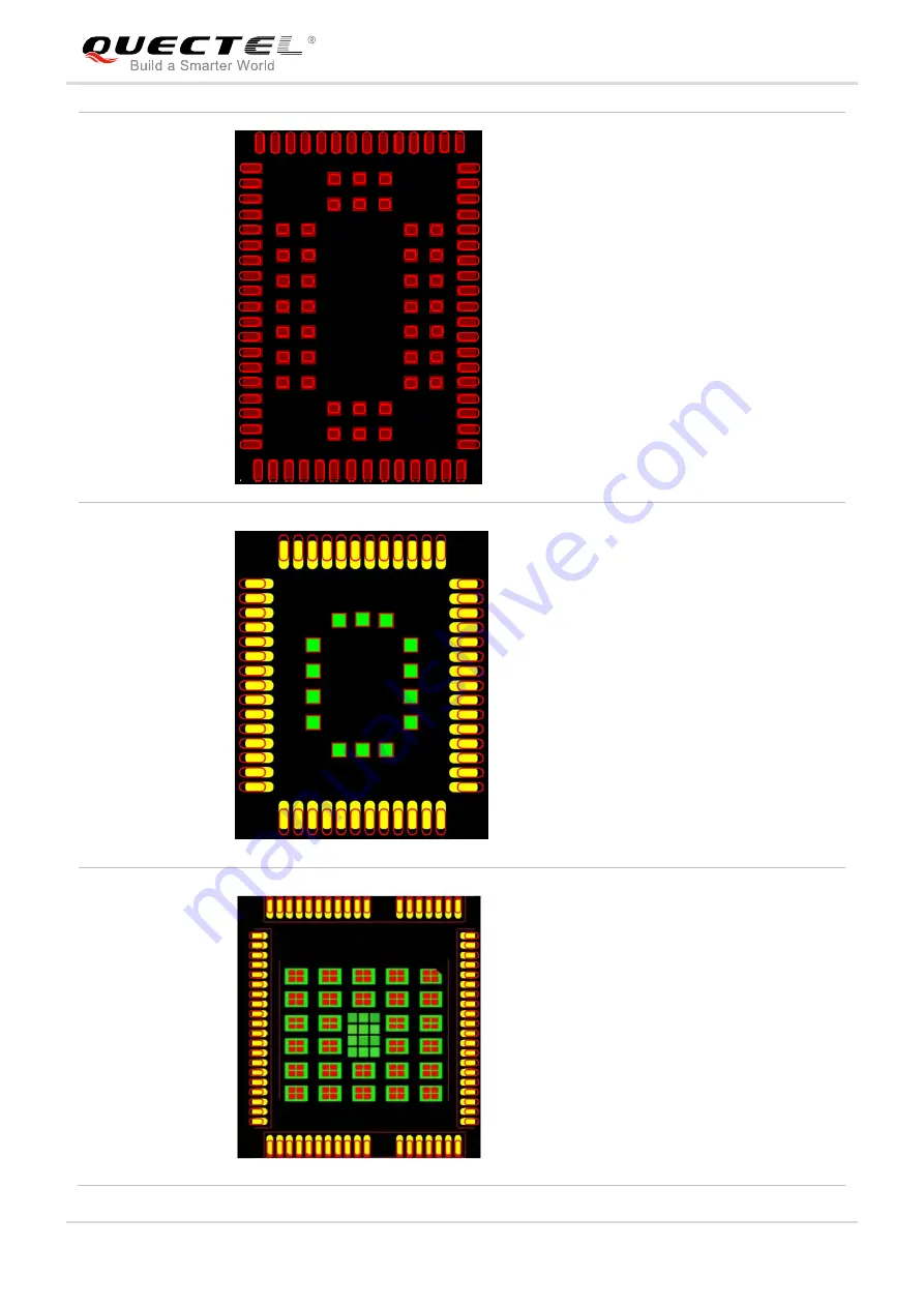
M89
1. The stencil thickness of the area for the
module should be partly stepped-up to
0.18-0.20mm.
2. For pads on four sides:
The innermost edge of the aperture for each
single pad should be shifted outward by
0.20mm and outermost edge should be
shifted outward by 0.40-0.60mm, and the
width should be reduced in a ratio of 1:0.85.
And the shape should be rectangle with
rectangle with round chamfer.
3. For pads in the center:
The stencil aperture for each single pad
should be centered with area reduced to
70%, and should be designed with round
chamfers.
MC60
1. The stencil thickness of the area for the
module should be partly stepped-up to
0.18-0.20mm.
2. For pads on four sides:
The innermost edge of the aperture for each
single pad should be shifted outward by
0.20mm and outermost edge should be
shifted outward by 0.40-0.60mm, while the
width should be reduced in a ratio of 1:0.85.
And the shape should be rectangle with
round chamfers.
3. For pads in the center:
The stencil aperture for each pad should be
centered with area reduced to 70%. The
shape should be square.
UC20/UC15
1. The stencil thickness of the area for the
module should be partly stepped-up to
0.18-0.20mm.
2. For pads on four sides:
The innermost edge of the aperture for each
single pad should be shifted outward by
0.20mm and the outermost edge should be
shifted outward by 0.40-0.60mm. The width
should be reduced in a ratio of 1:0.85. And
the shape should be rectangle with round
chamfers.
3. For GND pads in the center:
Design the stencil aperture for each pad into


