background image

Quasar CM-6208 User and Installation Guide 


68 


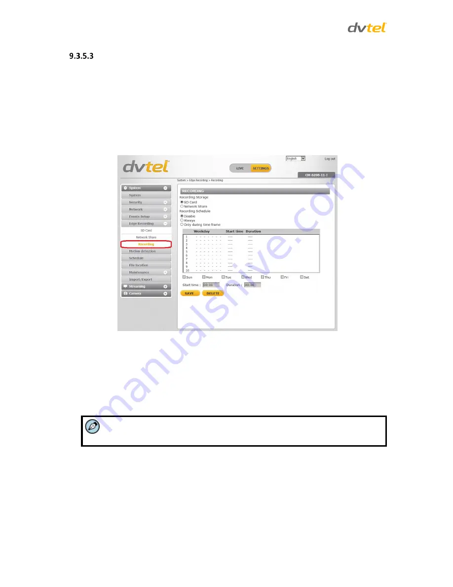
Recording 

The 

Recording

 screen is used to select a device and to set a schedule for recording clips. Up to 10 

schedules can be set. 

In the 

Recording Storage

 section, select the recording device: 

SD Card 

or 

Network Share

In the

 Recording Schedule

 section, specify the recording schedule. Select one of three options:  


Disable

 – Disable this function 


Always

 – Always use this function 


Only during time frame

 – Records only during a specified time frame 


 Figure 69: Recording Screen 

To set the recording schedule 

1.


Selecting the day. 

2.


Set the start time. 

3.


Set the duration for recording. 

4.


Click 

Save

 to confirm the schedule. The schedule is displayed in the table. 


Note:  

This option works only if (a) the microSDXC card is installed in the camera or (b) the 
NAS is configured properly.  

Summary of Contents for CM-6208

Page 1: ...era User and Installation Guide Rev A1 November 9 2014 DVTEL INC 65 Challenger Road Ridgefield Park NJ 07660 The contents of this guide may not be reproduced or reprinted in whole or in part without t...

Page 2: ...2 Outdoor Installation 11 5 3 Power and Ethernet Cable Connection 12 5 4 Initial Camera Configuration 12 5 5 Preparing the Camera for Use 14 5 6 Mounting Instructions 15 5 6 1 Mounting Tips 15 5 6 2...

Page 3: ...Video Mask 95 9 4 7 Audio 96 9 5 Camera Settings 97 9 5 1 Exposure 98 9 5 2 Picture Adjustment 101 9 5 3 Advanced Picture Settings 102 9 5 4 IR Function 105 9 5 5 Miscellaneous 107 9 6 Log Out 109 10...

Page 4: ...indow 23 Figure 27 Camera Tensioning Collar 25 Figure 28 CM 6208 Camera Pan Rotate and Tilt Angles 25 Figure 29 Browser Based User Interface 27 Figure 30 System Screen 31 Figure 31 Security System Scr...

Page 5: ...ter List Screen 82 Figure 86 Import Export Screen 82 Figure 87 File Download Screen 83 Figure 88 Streaming Tab 83 Figure 89 Video Rotate Type Screen 89 Figure 90 View 1 Source 89 Figure 91 View 2 Imag...

Page 6: ...vision History Version Date Author Comments 01 05 Sep Nov 2014 Alan Singer Preliminary releases A 0 6 Nov 2 2014 Alan Singer GA release Updated specifications A1 Nov 9 2014 Alan Singer Updated microSD...

Page 7: ......

Page 8: ...nes de s curit les normes et les codes lectriques ainsi que la l gislation en vigueur sur le lieu d implantation des unit s Proprietary Rights and Non Disclosure This manual is delivered subject to th...

Page 9: ...ion ou de mise en place de mesures de s curit insuffisantes Le non respect de tout ou partie des proc dures recommand es ou des messages d AVERTISSEMENT ou d ATTENTION de la part de l installateur du...

Page 10: ...task or procedure a user is carrying out or about to carry out WARNINGS and CAUTIONS are distributed throughout this document whenever applicable to alert the user of potentially hazardous situations...

Page 11: ...tez pas la cam ra et ne retirez pas ses vis Aucune pi ce se trouvant l int rieur de l unit ne n cessite un entretien par l utilisateur 4 Seul un technicien form et qualifi est autoris entretenir et r...

Page 12: ...ctor 5 If you use an extension cord with this system make sure that the total ampere rating on the products plugged into the extension cord does not exceed the extension cord ampere rating 6 To avoid...

Page 13: ...z une rallonge avec ce syst me assurez vous que l amp rage total des produits branch s sur la rallonge ne d passe pas l amp rage nominal de celle ci 6 Pour viter tout risque de choc lectrique ou d end...

Page 14: ...rence RFI To minimize the effects of EMI and RFI consult your reseller Minimisation des IEM et des IRF Lorsque des c bles parcourent une distance importante dans un champ lectromagn tique des interf r...

Page 15: ...or the type of video cabling used between the unit and the cameras and external devices Using a cable longer than the manufacturer s specifications for optimal video signal may result in degradation o...

Page 16: ...ples informations sur la configuration des param tres de la cam ra 2 1 Features H 264 and MJPEG compression HTTP streaming MJPEG Progressive scan CMOS sensor Edge motion detection Motion detection wit...

Page 17: ...dome camera Torx wrench Rubber washers 6 Self tapping screws 4 See note below Plastic screw anchors 4 CD Bundled software and documentation Quick Installation Guide Figure 1 Package Contents Note The...

Page 18: ...ed Typical CM 6208 Camera CM 6208 11 1 Motorized Camera Dimensions Internal Connectors Camera Connections 3 1 Typical CM 6208 Camera The figure below shows a typical CM 6208 camera Figure 2 Typical CM...

Page 19: ...button 2 Press the button for 30 seconds Both LEDs on the RJ45 connector are extinguished After one second the green network LED flashes once and then remains lighted The yellow activity LED flashes a...

Page 20: ...analog video output 3 4 1 Waterproofing the Camera Cable Connectors Follow the instructions below to waterproof the connectors for the different types of cables included in the system cable The cables...

Page 21: ...Plug the Ethernet cable to the connector of the RJ45 cable Figure 9 RJ45 Connector and Plug 2 Coat the joint with silicone gel Make sure there is no gap between the Ethernet cable and the connector i...

Page 22: ...66 rated RJ45 cable 8 Tighten the thread lock sealing nut to the plug Figure 13 Fastened Thread Lock Sealing Nut 3 4 2 Connecting Power to the Camera The camera can be powered by Power over Ethernet o...

Page 23: ......

Page 24: ...w Item Minimum System Requirement Personal Computer Minimum Intel Core i5 2430M 2 4 GHz 4GB RAM Recommended Intel Core i7 870 2 93 GHz 8GB RAM Operating System Windows XP Windows 7 Windows 8 Windows 8...

Page 25: ......

Page 26: ...ver spray etc Do not place the camera on or near radiators and heat sources All electrical work must be performed in accordance with local regulatory requirements 5 2 Outdoor Installation Read the ins...

Page 27: ...k Cat 5 Ethernet cable to the RJ45 connector on the camera s system cable 6 Connect the other end of the network cable to a Power Sourcing Equipment PSE device such as a switch 7 Verify that the LEDs...

Page 28: ...Netmask Click Update and wait for OK status to be displayed Figure 15 DNA Assign IP Dialog Box Disconnect the Ethernet cable The camera is ready for deployment mounting in a site installation Note 1 T...

Page 29: ...for shipping from the factory Releasing the lens assembly for use 1 Removed the mini dome cover by opening the rubber tabs and unscrewing the screws located under the tabs with the star bit tool supp...

Page 30: ...e rubber tabs back into position 5 6 Mounting Instructions The following are mounting instructions for the CM 6208 series cameras CM 6208 11 I Mounting Tips Mounting the CM 6208 11 I for Indoor or Out...

Page 31: ...on holds firm after the screws are screwed in c Fully insert the supplied anchors into drilled holes You may need to tap them flush with the wall using a hammer For installing on a 4S recessed electri...

Page 32: ...the Cat 5 cable into the camera s Ethernet port and if needed plug the power terminal block into the power terminals 5 If applicable wire the Alarm In Alarm Out Audio In and Audio Out terminal blocks...

Page 33: ......

Page 34: ...essible over the network Once listed each camera can be right clicked to access and change the network settings If the network settings are changed for some reason a new search will relist the units T...

Page 35: ......

Page 36: ...DNA icon Note DNA is an alternative software to Device Search Either of these programs may be used 3 In the DNA application click the DNA button 4 If the Windows Firewall is enabled a security alert...

Page 37: ...Select Use DHCP Do not use for Latitude ii Click Update and wait for status For Static IP recommended for Latitude users Figure 24 DNA Assign IP Static IP Dialog Box i Do not select the Use DHCP chec...

Page 38: ...ht click on the Information Bar Select Install ActiveX Control to allow the installation Figure 25 Installing the ActiveX Control If a security warning window prompt appears click Install Figure 26 Se...

Page 39: ......

Page 40: ...prompts for login do the following a Log in using the default user name Admin and password 1234 If the password has previously been changed use the new password Note Both the user name and password a...

Page 41: ...ens iris is fully open such as at night in low light This prevents loss of sharpness if light levels are reduced at night 7 To achieve optimum focus results during daytime open the Camera Exposure scr...

Page 42: ...scribed in detail Additionally if DVTEL s Latitude VMS is used many of the configurations and features of DVTEL s VMS provide configuration and automation of the camera This section includes the follo...

Page 43: ...s are discussed in Streaming Settings Camera Settings The administrator can adjust many of the camera settings on this page such as Exposure Picture Adjustment IR Function Digital Zoom and TV System D...

Page 44: ...the local site to talk to the remote site Click the button to switch it on off This function is available only to a user who has been granted this privilege by the Administrator Refer to User in the...

Page 45: ...y focus Step Near Far Press the Near Step or Far Step button to alternate the focus between near and far views within a user defined range which can be selected from the drop down menu Step Range Sele...

Page 46: ...ludes the following fields Host Name The host name is for camera identification If the alarm function is enabled and is set to send an alarm message by Mail or FTP the host name entered here is displa...

Page 47: ...be identical with that displayed to the right of the text box Sync with NTP Server Network Time Protocol NTP is an alternate way to synchronize the camera s clock with an NTP server Enter the network...

Page 48: ...d A Z a z 0 9 _ Add user The user name and passwords are limited to 14 characters There is a maximum of 20 user accounts To add a new user 1 Type the new user name and password in the respective field...

Page 49: ...uses unencrypted base64 encoding Basic Authentication should generally only be used where transport layer security such as HTTPS is provided Digest A form of authentication used over RTSP in which cr...

Page 50: ...ab in the sidebar to display the following screen Figure 34 Security HTTPS Screen To create a self signed certificate Before a CA issued certificate is obtained users can first create and install a se...

Page 51: ...r the local administrative region Locality Enter other geographical information Organization Enter the name of the organization to which the entity identified in Common Name belongs Organizational Uni...

Page 52: ...roperties dialog box If you want to remove the certificate click Remove Figure 38 Certificate Properties 5 When the signed certificate is returned from the CA click Browse in the Install Signed Certif...

Page 53: ...t 1 Click Create Certificate Request to create and submit a certificate request in order to obtain a signed certificate from a CA Figure 40 HTTPS Screen Install Signed Certificate The Create Certifica...

Page 54: ...rganizational Unit Enter the name of the organizational unit to which the entity identified in the Common Name field belongs Common Name Indicate the name of the person or other entity that the certif...

Page 55: ...page Figure 44 IP Filter Screen To enable the IP filter 1 Check the box to enable the IP filter function Once enabled the listed IP addresses IPv4 are allowed or denied access to the camera 2 Select...

Page 56: ...ficate to check the server s identity Client Certificate Upload the Client Certificate to authenticate the camera Click Browse to locate the file and Upload to upload the certificate Private Key Uploa...

Page 57: ...otocol over Ethernet support for users who connect to the network via PPPoE The Basic screen is divided into three sections General Advanced and IPv6 Configuration See Figure 46 Network Screen General...

Page 58: ...addresses Secondary DNS A secondary domain name server that backs up the primary DNS Use PPPoE To use PPPoE 1 Enter your PPPoE user name and password into the respective fields 2 Click Save to confirm...

Page 59: ...receive the corresponding forwarding treatment from DiffServ capable routers Figure 47 QoS Screen DSCP Settings The DSCP value range is from 0 to 63 The default DSCP value is 0 DSCP disabled The came...

Page 60: ...objects The default value is private SNMP v3 SNMP v3 provides important security features including Confidentiality Encryption of packets to prevent snooping by an unauthorized source Integrity Messa...

Page 61: ...eck this box to activate trap reporting Trap address Enter the IP address of the management server Trap community Enter the community to use when sending a trap message to the management system The de...

Page 62: ...unction make sure the UPnP component is installed on your computer Refer to Install UPnP Components for the Windows 7 Windows 8 and Windows 8 1 procedure Enable UPnP port forwarding When UPnP port for...

Page 63: ...Figure 51 DDNS Screen To use DDNS Select the Enable DDNS checkbox From the Provider drop down list select a DDNS host provider name In the Host name text box enter the registered domain name In the Us...

Page 64: ...SMTP server accounts can be configured Enter the settings for the 1st SMTP server and 2nd SMTP server in the appropriate fields Settings include SMTP server server port default port is 25 account nam...

Page 65: ...ving the problem of firewalls filtering the incoming data port connection to the client from the server In order to support passive mode FTP on the server side firewall the following communication cha...

Page 66: ...ggered and Motion Detection can be set up and sent to the specified HTTP servers For each server enter the HTTP details including server IP address user name and password Click Save when finished The...

Page 67: ...to enable an alarm default setting Select By Schedule to set a schedule Then click Please Select to select up to 10 schedules from the drop down list that opens The selected schedules are displayed in...

Page 68: ...number of frames for the buffer from 1 20 frames Figure 56 Trigger Action Upload Image by FTP Select the Continue image upload checkbox to upload an image by FTP for a defined period of time or while...

Page 69: ...buffer drop down lists select the number of frames for the buffer from 1 20 frames Figure 58 Triggered Action Upload Image by E Mail Check the Continue image upload box if you wish to upload an image...

Page 70: ...mage s file name format is set in this section Select one that meets your requirements Add date time suffix default setting File name imageYYMMDD_HHNNSS_XX jpg Y Year M Month D Day H Hour N Minute S S...

Page 71: ...n alarm Select By Schedule to set a schedule Then click Please Select to select up to 10 schedules from the drop down list that opens The selected schedules are displayed in the Please Select text box...

Page 72: ...and that the NAS is properly configured See Recording for further details Send message by E Mail Select whether to send an alarm message by e mail when a network failure is detected Save Click Save t...

Page 73: ...able alarm relay when tampering is detected Send Alarm Message by FTP The Administrator can select whether to send an alarm message by FTP when tampering is detected Upload Image by FTP Selecting this...

Page 74: ...e Video Resolution screen Specify two e mail addresses to use from the drop down menu Select the number of frames for the pre trigger and post trigger buffers from the drop down menu of 1 20 frames Ch...

Page 75: ...ds for the minimum interval between alarms Triggered Action The Administrator can specify multiple alarm actions to be taken when a triggering event occurs The options are listed as follows Enable ala...

Page 76: ...ad Image by E Mail Selecting this option enables you to assign an e mail address and configure various parameters as shown in Figure 58 Triggered Action Upload Image by E Mail When tampering is detect...

Page 77: ...suffix limited value File Name imageXX jpg X Sequence Number The file name suffix ends at the number being set For example if the setting is up to 10 the file name will start from 00 end at 10 and the...

Page 78: ...selected as the video stream from the Video Resolution screen Specify two e mail addresses to use from the drop down menu Select the number of frames for the pre trigger and post trigger buffers from...

Page 79: ...saved on the memory card You can also format the card and implement automatic recording cleanup on this page To implement microSDXC card recording see Recording Figure 64 SD Card Screen Note Format t...

Page 80: ...stem immediately saves a recorded event on the memory card once an event occurs Then the camera will return to the regular recording mode after events recording Figure 65 Video File Recording List Rem...

Page 81: ...er accessing the NAS Password Displays the password of the user accessing the NAS Storage Tools Click Format to format the NAS Disk Cleanup Setting Enable automatic recording cleanup by selecting Enab...

Page 82: ...schedule N Network failure M Motion M0 refers to the first motion window trigger A Alarm A0 refers to the first alarm trigger input Download To open download a video clip first select the file and th...

Page 83: ...y the recording schedule Select one of three options Disable Disable this function Always Always use this function Only during time frame Records only during a specified time frame Figure 69 Recording...

Page 84: ...t outward or inward Moving the mouse to the center of the frame shifts the frame to the intended location Motion Detection Activation It is possible to define up to four motion detection zones within...

Page 85: ...tection Screen with Schedule Drop Down Menu Motion Detection Windows Up to 10 Motion Detection windows can be set Press the Add button under the Live View pane to add a Motion Detection window To canc...

Page 86: ...window will be lowered accordingly Time interval sec 0 7200 Select a number from 0 7200 seconds The default interval is 10 The value is the interval between each detected motion Triggered Action The A...

Page 87: ...ee Figure 57 Send HTTP Notification Option Send alarm message by E Mail Select whether to send an alarm message by e mail when motion is detected Note Make sure that local recording with a microSDXC c...

Page 88: ...camera using the available dropdown See Figure 75 Schedule Screen Note This application is not the same as the Recording Schedule function Figure 75 Schedule Screen To create a new schedule or edit a...

Page 89: ...page specify a storage location for snapshots and web recordings The default setting is C After confirming the setting click Save to save the snapshots and recordings in the designated location Note M...

Page 90: ...9 3 9 Maintenance Clicking the Maintenance tab in the System screen opens a drop down menu with the following tabs Log File User Information Factory Default Software Version Software Upgrade Paramete...

Page 91: ...See Figure 77 System Log Screen User Information The Administrator can view each user s login information and privileges in the User information screen shown below View User Login Information Click ge...

Page 92: ...s privileges Figure 79 User Information Privileges Screen In the screen above the user Admin is granted privileges of I O access Camera control Talk and Listen Note The example above shows the maximum...

Page 93: ...low the instructions to reset the camera to factory default settings if needed Figure 80 Factory Default Screen Full Restore Click Full Restore to restore the factory default settings The system resta...

Page 94: ...ngs but save the network settings The system restarts in 30 seconds Figure 81 Partial Restore Screen Reboot Clicking Reboot restarts the system without changing current settings Software Version The c...

Page 95: ...ore performing a software upgrade To upgrade the software 1 In the Step 1 text box click Browse and select the binary file to be uploaded for example uImage userland img Note Do not change the upgrade...

Page 96: ...ss is completed the Home page is displayed Figure 84 Software Upgrade In Process 4 Close the video browser 5 From the Windows Start menu select Control Panel 6 Select Uninstall a Program 7 In the Curr...

Page 97: ...ure 85 Parameter List Screen Note Slide the sidebar located on the right of the screen to view the entire list of parameters 9 3 10 Import Export From the Import Export screen you can export configura...

Page 98: ...tion to save the configuration file Warning Do not unplug power while changing file names Upload To copy an existing configuration file to the camera click Browse to select the configuration file and...

Page 99: ...264 MJPEG H 264 H 264 H 264 H 264 H 264 H 264 H 264 MJPEG H 264 Only H 264 Only PAL 25 FPS NTSC 30 FPS PAL 50 FPS NTSC 60 FPS 3840 x 2160 24 fps 3840 x 2160 24 fps 3840 x 2160 24 fps 3840 x 2160 24 f...

Page 100: ...1024 x 768 25 fps 1024 x 768 30 fps 1024 x 768 50 fps 1024 x 768 60 fps 800 x 600 25 fps 800 x 600 30 fps 800 x 600 50 fps 800 x 600 60 fps 720 x 576 25 fps 720 x 480 30 fps 720 x 576 50 fps 720 x 480...

Page 101: ...fps 3840 x 2160 15 fps 1920 x 1080 25 fps 1920 x 1080 30 fps 1920 x 1080 50 fps 1920 x 1080 60 fps 1280 x 1024 25 fps 1280 x 1024 30 fps 1280 x 1024 50 fps 1280 x 1024 60 fps 1280 x 720 25 fps 1280 x...

Page 102: ...x 600 30 fps 720 x 576 25 fps 720 x 480 30 fps 720 x 576 50 fps 720 x 480 30 fps 640 x 480 25 fps 640 x 480 30 fps 352 x 288 25 fps 352 x 240 30 fps 320 x 240 25 fps 320 x 240 30 fps H 264 H 264 H 264...

Page 103: ...0 30 fps 320 x 240 50 fps 320 x 240 60 fps H 264 H 264 H 264 MJPEG Stream 3 1280 x 720 25 fps 1280 x 720 30 fps 1280 x 720 25 fps 1280 x 720 30 fps 1024 x 768 25 fps 1024 x 768 30 fps 1024 x 768 25 fp...

Page 104: ...gree counterclockwise Differences among these types are illustrated below The following drop down menu appears when selecting this option Figure 89 Video Rotate Type Screen Suppose the displayed image...

Page 105: ...ines 21 sets of capabilities These are referred to as profiles and they target specific classes of applications In the security industry the most common are as follows Baseline Profile BP Primarily fo...

Page 106: ...ng of H 264 1is 4096 The default setting for H 264 2 H 264 3 and H 264 4 is 1024 kbps The setting range is from 64 to 20 480 kbps Click Save to confirm the setting Note A total of 26 624Kbps is availa...

Page 107: ...Interest settings for four H 264 streams and one MJPEG stream on the Video ROI screen The image displayed within the ROI box is displayed with higher bit rate and quality than the image outside of th...

Page 108: ...Protocol Screen Video OCX protocol setting options include RTP over UDP RTP over RTSP TCP RTSP over HTTP MJPEG over HTTP Multicast mode Enter in each field all required data including Multicast IP ad...

Page 109: ...etting range for the H 264 1 Frame Rate is from 1 to 15 in NTSC and 1 to 13 in PAL The default setting is 15 fps in NTSC and 13 fps in PAL H 264 2 The setting range for the H 264 2 Frame Rate is from...

Page 110: ...ocked out or obscured from view To enable a mask 1 Check a Video Mask checkbox A red frame is displayed in the Live Video pane on the right side 2 Use the mouse to drag and drop adjust the mask s size...

Page 111: ...nly Simplex mode the local remote site can only talk to the other site Simplex Listen only In the Listen only Simplex mode the local remote site can only listen to the other site Disable Select this o...

Page 112: ...t setting is Disabled Note This function works only if the Recording to Storage option has been selected or if the Schedule option has been set Click Save to confirm the settings 9 5 Camera Settings F...

Page 113: ...exposure level using a programmed algorithm or choose the level themselves Even in Auto Shutter a Minimum Shutter Speed may be set from the drop down menu to ensure a maximum level of exposure In Man...

Page 114: ...L See the table below showing all the options Auto Iris Min Shutter Speed PAL NTSC 1 25 1 30 1 12 1 15 1 6 1 8 1 3 1 4 1 1 5 1 2 1 Auto Shutter Min Shutter Speed When selecting this mode the camera s...

Page 115: ...utter Manual Mode opens the iris completely with a fixed gain Users can select a suitable shutter speed according to the environmental luminance The fixed shutter speed is selected from 1 to 1 10000 s...

Page 116: ...s controlling the video gain from Off or in steps from 1 to 9 Click Set when you finish setting the gain 9 5 2 Picture Adjustment Adjustment of some qualities of the video is made possible by selectin...

Page 117: ...p down menu for controlling the camera s white balance color balance Figure 101 Advanced Picture Settings Screen White Balance A camera needs to find a reference color temperature as a way of measurin...

Page 118: ...t with a light source color temperature in the range of approximately 2500 10 000K One Push This button activates the factory optimized setting for white balance This setting may not be ideal for ever...

Page 119: ...r changing light issues in order to enhance the video display The WDR is adjustable among Off Low Mid and Hi A higher level of WDR represents wider dynamic range so that the IP camera can capture a gr...

Page 120: ...he new settings Figure 104 Advanced Picture Settings Screen Noise Reduction 9 5 4 IR Function The IR Function setting activates two functions It activates the IR LED illuminator for use in low light c...

Page 121: ...ing is used in low light conditions or at night IR LED lights are turned On or Off depending on the light sensor The default mode is Auto Two settings are available Auto The light sensor operates auto...

Page 122: ...m the Misc Miscellaneous tab you can set the Digital Zoom and TV System Digital Zoom The camera s digital zoom is adjustable from x2 to x10 Select the desired zoom or Off Click Set to confirm the new...

Page 123: ...60 fps NTSC 50 fps PAL 30 fps NTSC or 25 fps PAL Click Set to confirm the new setting Figure 107 Camera Settings Screen TV System Note After changing the video format the camera restarts automatically...

Page 124: ...nd Operation 109 9 6 Log Out Selecting the Logout link on the Home page to close the session The following message appears Figure 108 Login Message Upon clicking Login the Login window opens Figure 10...

Page 125: ......

Page 126: ...echnical Specifications Device Search Software Internet Security Settings Install UPnP Components Deleting Existing DVPlayer Deleting Temporary Internet Files Connecting Leads to a Spring Clamp Termin...

Page 127: ...2 fps PAL Rate Control Option CBR 64Kbps 20 480Kbps VBR Operation Image Setting Brightness Manual Exposure Auto iris Auto Fixed Shutter Sharpness Manual Contrast Manual Hue Manual White Balance Auto I...

Page 128: ...0Mbps Ethernet Auto sensing Full Half Duplex Protocols IPv4 v6 TCP IP UDP RTP RTSP HTTP HTTPS ICMP FTP SMTP DHCP PPPoE UPnP IGMP SNMP SNTP QoS IEEE 802 1X ONVIF Version 2 4 Profile S Password Levels U...

Page 129: ...ter and IR Power Source 12VDC 10 24VAC 10 PoE 802 3af Class 0 Environmental Operating Temperature 40 to 50 C 40 to 122 F with heater Humidity 10 95 non condensing General Regulatory US FCC 47 CFR Part...

Page 130: ...Tools and select Internet Options from the menu that appears Figure 110 Command Bar Toolbar Select Internet Options 3 In the Internet Options window that appears select the Security tab 4 Select in S...

Page 131: ...Level 5 In the dialog that appears under ActiveX controls and plug ins set ALL the following options listed below to Enable or Prompt Automatic prompting for ActiveX controls Binary and script behavio...

Page 132: ...PnP so that the camera can be discovered and displayed in Network locations under Other Devices To enable UPnP discovery in Windows 7 and Windows 8 1 Click Start and select Control Panel 2 Click on Ne...

Page 133: ...ate through Windows Firewall and that other firewalls are not interfering with network discovery To check that the UPnP Device Host services are running 1 Click Start and type in the Search programs a...

Page 134: ...d first delete the existing DVPlayer from the PC before accessing the camera To delete a legacy DVPlayer 1 Click Start and select Control Panel 2 In the Control Panel click Uninstall a program 3 From...

Page 135: ...s To delete temporary Internet files 1 In Internet Explorer IE from the Command Bar toolbar click Tools and select Internet Options from the menu that appears 2 In the General tab in the Internet Opti...

Page 136: ...t Fixed Dome IP Camera For more information on available options contact your DVTEL sales representative or visit www DVTEL com to request details on where to get the accessories you need Image Name D...

Page 137: ...Corner Bracket fits CX ARMX 0 and CX ARMX 1 CX F120 1 Pendant Mounting Adapter Ring adapts all pendant cameras to common legacy 1 1 2 female pipe mounts Fits DVTEL legacy mounts and many others CX PIP...

Page 138: ...Mounting Accessories 123 Image Name Description CX POLE 0 Pole Mount Bracket fits CX ARMX 0 and CX ARMX 1 CX WLBX 0 Wall Mount Box fits CX ARMX 0 and CX ARMX 1...

Page 139: ...8235 9211 Fax 61 8 8235 9255 info anz DVTEL com EMEA DVTEL UK Ltd 7 Lancaster Court Coronation Road High Wycombe HP12 3TD England Tel 44 0 1494 412240 Fax 44 0 1494 446928 info uk DVTEL com INDIA AND...

Reviews: