


QUANTECH
79
SECTION 5 - COMMISSIONING
FORM QWC4-NM1 (221)
ISSUE DATE: 02/28/2021
5
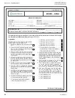
QUANTECH
2
FORM QWC4-CL3
ISSUE DATE: 02/28/2021
ADJUSTMENT
SETTING VALUE
Long Time Pickup IR~
G
Long Time Delay TLD(S) LONG
2
Short Time Delay ISD(XIR)
SHORT
2
Ground Fault Pickup IG(XIN)
GND
0.2
Ground Fault Delay TSD/
TG(MS) SHORT/GND
J
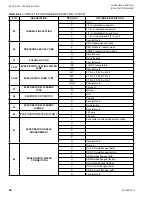
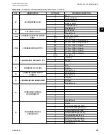
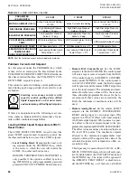
Find your model from the list below, check the ratings
plug values in the first table, and set the setting values
for the adjustments listed in the second table:
DRIVE MODEL NO.
RATINGS PLUG VALUE
TVP1CMPRBW_-50B
600
TVP1CMPRBW_-65B
600
TVP1CMPRBW_-68B
600
ADJUSTMENT
SETTING VALUES
Short Delay Pick-up
2
Short Delay Time
INST
Ground Fault Pick-up
1
Ground Fault Time
150
The settings for the circuit breaker should
not be changed from the settings. The war-
ranty will be voided if the breaker settings
are changed.
13. Check the chiller for refrigerant leaks at joints or
water piping leaks. .............................................
14. Make sure 9 liters of compressor oil were added
to both circuits. ...................................................
15. Make sure the control panel is free of foreign
material (wires, metal chips, tools, documents,
etc.). Check for signs of water or moisture. .......
16. Make sure the leaving liquid temperature sensor
is coated with the heat conductive compound
(P/N 013-00890-000), and is inserted to the bot-
tom of the water outlet sensor well in the cooler.
This sensor must always be fully inserted in the
water outlet sensor well. ....................................
17. Make sure the flow switches are connected be-
tween Terminals 2 and 12 and 2 and 13 on Ter-
minal Block 1TB in the control panel. .................
18. Check whenever the pump contacts are used,
the coil of the pump starter should be suppressed
with an RC suppressor (P/N 031-00808-000). ...
B. START-UP
Panel Check
Only qualified individuals are permit
-
ted to service this product, and are to
be knowledgeable of, and adhere to, all
safe work practices as required by local
codes. Use proper personal protection
where and when required.
1. Verify that the voltage supply corresponds to
the unit requirement, and is within the limits as
specified in SECTION 4 - TECHNICAL DATA in
Form
QWC4-NM1.
.............................................
2. Make sure the unit switch at the bottom of the
keypad is in the OFF (O) position. .....................
3. Apply 3-phase power to the chiller. Turn on the
optional panel circuit breaker, if supplied. ..........
4. Verify the control panel display is illuminated.
To prevent the compressors from starting, make
sure that the SYSTEM SWITCHES key is off for
both systems. . ....................................................
5. Use a clamp-on ammeter to make sure the both
compressor heaters are turned on. Heater cur-
rent draw is approximately 3A. ...........................
6. Confirm that the compressor overload current
settings have been correctly adjusted by the fac-
tory. These are not normally required to be re-
set. Use the VSD DATA key on the control panel,
navigate to the COMP1 MOTOR OVERLOAD =
### AMPS and COMP2 MOTOR OVERLOAD
= ### AMPS screens. The values should match
the values on the overload setting label, which is
located inside of the VSD cabinet. If the values
do not match, an adjustment is required inside
the VSD cabinet by qualified service personnel. .
7. Record the overload settings below:
System 1: __________________________Amps
Setting the motor overload potentiom
-
eters incorrectly may cause damage to
the equipment.
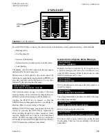
8. Press the STATUS key. If the following UNIT
WARNING message appears, immediately con-
tact QuanTech Product Technical Support to
request the password to reprogram the serial
number, and any other important factory pro-
grammed information that was lost. . .......................
9. If the unit is equipped with SC-EQ, set up per
450.50-N1 Section 2
............................................
UNIT WARNING: INVALID SERIAL NUMBER
ENTER UNIT SERIAL NUMBER
(Continued on following page)
Summary of Contents for QWC4
Page 14: ...QUANTECH 14 FORM QWC4 NM1 221 ISSUE DATE 02 28 2021 THIS PAGE IS INTENTIONALLY LEFT BLANK...
Page 64: ...QUANTECH 64 FORM QWC4 NM1 221 ISSUE DATE 02 28 2021 THIS PAGE IS INTENTIONALLY LEFT BLANK...
Page 82: ...QUANTECH 82 FORM QWC4 NM1 221 ISSUE DATE 02 28 2021 THIS PAGE IS INTENTIONALLY LEFT BLANK...
Page 130: ...QUANTECH 130 FORM QWC4 NM1 221 ISSUE DATE 02 28 2021 THIS PAGE IS INTENTIONALLY LEFT BLANK...
Page 146: ...QUANTECH 146 FORM QWC4 NM1 221 ISSUE DATE 02 28 2021 THIS PAGE IS INTENTIONALLY LEFT BLANK...
Page 152: ...QUANTECH 152 FORM QWC4 NM1 221 ISSUE DATE 02 28 2021 THIS PAGE IS INTENTIONALLY LEFT BLANK...
Page 155: ...QUANTECH 155 NOTES...