


QUANTECH
59
SECTION 3 - HANDLING, STORAGE, INSTALLATION, AND REASSEMBLY
FORM QWC4-NM1 (221)
ISSUE DATE: 02/28/2021
3
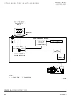
How To Receive Voltage Or Current Signal
The control board JUMPER JP4 must be positioned
correctly to receive a voltage (0-10 VDC or 2-10 VDC)
or a current (0 mA to 20 mA or 4 mA to 20 mA) signal.
Place the jumper in the
V
position for a
voltage
sig-
nal, or
mA
for a
current
signal. Configure the software
under the OPTIONS key for the specific type of input
signal to be used.
The maximum temperature reset (100%) is achieved at
either 10 VDC or 20 mA. Sending the minimum signal
(0 VDC or 2 VDC, 0 mA or 4 mA, based on the OP-
TIONS key) causes the setpoint to revert back to its lo-
cal programmed value. If the setpoint reset causes the
setpoint to go over the maximum programmable value,
it will be set to the maximum programmable setpoint.
0 VDC to 10 or 2 VDC to 10 VDC Reset Input
A 0 VDC or 2 VDC signal produces a 0°F (0°C) re-
set. A 10 VDC signal produces a 100% (max.) reset
(SETPOINTS key). The setpoint reset is ramped lin-
early between these limits as the input varies between 0
or 2
VDC and 10 VDC. For this input to work properly,
the Remote Temperature Reset must be programmed
for 0 VDC to 10 VDC or 2 VDC to 10 VDC input (OP-
TIONS key) and control board JUMPER JP4 placed in
the
V
position.
0 mA to 20 mA or 4 mA to 20 mA Reset Input
A 0 mA or 4
mA signal produces a 0°F (0°C) reset. A 20
mA signal produces 100% (max.) reset (SETPOINTS
key). The setpoint reset is ramped linearly between
these limits as the input varies between 0 mA or 4 mA
and 20 mA. In order for this input to work properly,
program the Remote Temperature Reset for 0 mA to 20
mA or 4 mA to 20 mA input (OPTIONS) and control
board JUMPER JP4 placed in the
mA
position.
Leaving Condenser Liquid Temperature Reset
Control
The same input used for Leaving Chilled Liquid Tem-
perature Reset is used for Leaving Condenser Liquid
Temperature Reset when the heat pump option is in-
stalled. The function of the input is controlled by se-
lecting the operating mode described in
in this manual.
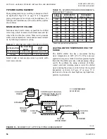
Current Limit Reset Control
Install input for Current Limit Reset Control across
Terminals 19 (+) and 20 (-) of the 1TB Terminal Block.
How to Receive Voltage or Current Signal
The control board JUMPER JP5 must be positioned
correctly to receive a voltage (0 VDC to 10 VDC or 2
VDC to 10 VDC) or a current (0 mA to 20 mA or 4 mA
to 20 mA) signal. Place the jumper in the
V
position for
a voltage signal or
mA
for a current signal. Configure
the software under the OPTIONS key for the type of
input signal to be used.
The minimum current limit setpoint is achieved at ei-
ther 10 VDC or 20 mA. Sending the minimum signal
(0 VDC or 2 VDC, 0 mA or 4 mA, based on the OP-
TIONS key) causes the current limit to revert back to
its maximum value.
0 VDC to 10 VDC or 2 VDC to 10 VDC Reset
Input
A 0 VDC or 2 VDC signal produces a 0°F (0°C) re-
set. A 10 VDC signal produces a 100% (max.) reset
(SETPOINTS key). The setpoint reset is ramped lin-
early between these limits as the input varies between
0 VDC or 2
VDC and 10 VDC. In order for this input
to work properly, the Remote Temperature Reset must
be programmed for 0VDC to 10 VDC or 2 VDC to 10
VDC input (OPTIONS key) and control board JUMP-
ER JP5 placed in the
V
position.
0 mA to 20 mA or 4 mA to 20 mA Reset Input
A 0 mA or 4
mA signal produces a 0°F (0°C) reset. A 20
mA signal produces 100% (max.) reset (SETPOINTS
key). The setpoint reset is ramped linearly between
these limits as the input varies between 0 mA or 4 mA
and 20 mA. In order for this input to work properly,
the program the Remote Temperature Reset for 0 mA
to 20 mA or 4 mA to 20 mA input (OPTIONS key) and
control board JUMPER JP5 placed in the
mA
position.
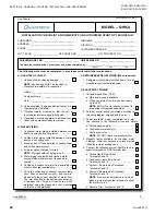
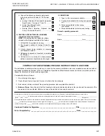
INSTALLATION CHECKLIST – REQUEST FOR
START-UP SERVICE
When all items on the
Installation Checklist and
Request for Authorized Start-up Technician
(Form
QWC4-CL1)
(North America Only)
are completed
satisfactorily, and before any attempt is made to start
the unit, contact the Quantech Field Service Office to
schedule the start-up service.
Summary of Contents for QWC4
Page 14: ...QUANTECH 14 FORM QWC4 NM1 221 ISSUE DATE 02 28 2021 THIS PAGE IS INTENTIONALLY LEFT BLANK...
Page 64: ...QUANTECH 64 FORM QWC4 NM1 221 ISSUE DATE 02 28 2021 THIS PAGE IS INTENTIONALLY LEFT BLANK...
Page 82: ...QUANTECH 82 FORM QWC4 NM1 221 ISSUE DATE 02 28 2021 THIS PAGE IS INTENTIONALLY LEFT BLANK...
Page 130: ...QUANTECH 130 FORM QWC4 NM1 221 ISSUE DATE 02 28 2021 THIS PAGE IS INTENTIONALLY LEFT BLANK...
Page 146: ...QUANTECH 146 FORM QWC4 NM1 221 ISSUE DATE 02 28 2021 THIS PAGE IS INTENTIONALLY LEFT BLANK...
Page 152: ...QUANTECH 152 FORM QWC4 NM1 221 ISSUE DATE 02 28 2021 THIS PAGE IS INTENTIONALLY LEFT BLANK...
Page 155: ...QUANTECH 155 NOTES...