


QUANTECH
133
SECTION 7 - MAINTENANCE
FORM QWC4-NM1 (221)
ISSUE DATE: 02/28/2021
7
fied technician should confirm the compressor
oil heater is working properly, and is energized.
If it is the first start-up for the cooling season, the
technician should confirm the oil heater has been
energized for at least 24 hours before start-up.
During start-up, the chiller should be manually
unloaded until a discharge superheat temperature
(displayed on the SYSTEM DATA key) of 18°F
(10°C) or greater is maintained and liquid level
drops below the top of the upper sight glass on
the oil separator. The chiller should continue to
be held in part-load operation until the foaming
in the oil separator is minimized. The chiller can
then be returned to the position or load control to
meet the cooling load requirements.
Operation
1.
Oil level should be visible in or below the upper
sight glass:
If the chiller operates in a low dis-
charge superheat condition for an extended period
of time, refrigerant can condense in the oil separa-
tor. Unload and hold the chiller at a capacity that
allows the discharge superheat to increase above
18°F (10°C), and until the level drops below the
top of the upper sight glass and foaming is mini-
mized. The chiller can then be loaded normally as
the building/process load requires.
2. If there is no visible oil in either sight glass, a
problem may exist with the oil return system. If
load is such that the compressor is operating at
least 100
Hz,
the oil should be present in the sight
glass. At lower loads, oil level may be below the
lower sight glass. If the proper amount of oil is in
the chiller, the bearings will be adequately lubri-
cated. The chiller should be loaded when validat-
ing oil capacity in the chiller. A qualified techni
-
cian should add only enough oil to create a visible
level in the bottom of the lower sight glass.
Start the chiller and run a load condition between
65% and 80% FLA for a minimum of one hour,
and then observe the oil level. The oil level should
become visible in either the lower or upper sight
glass, depending on conditions. A qualified techni-
cian should then remove the approximate amount
added to start the chiller.
Oil Analysis
Complete an annual oil analysis to verify the continued
use of the compressor oil.
The oil sample should not be exposed to
the atmosphere for more than 15 minutes
because it will absorb moisture from the
atmosphere and may yield erroneous
results.
Change the compressor oil when the oil analysis indi-
cates that the oil has moisture, and the acid numbers
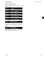
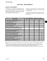
TABLE 43 -
COMPRESSOR OIL LIMITS
MOISTURE
YORK OIL
TYPE
MOISTURE
CONTENT
(KARL FISHER
METHOD) PPM
TAN
(TOTAL ACID
NUMBER)
MGKOH/ML
L
< 300
< 0.5
The QWC4 chiller compressors use rolling element
bearings (ball and roller bearings); no sleeve bear-
ings are used. Oil analysis that include metals, such as
iron, copper, titanium, zinc, lead, tin and silicon, may
cause confusion when the results are compared to oth-
er equipment that use different bearing types. Ignore
these metals in the oil analysis because they are ac-
ceptable if < 100 ppm. If an oil analysis indicates >300
ppm of iron, combined with > 50 ppm of chromium
and nickel, consult the Quantech Field Service Office
because these amounts could indicate bearing damage
and wear.
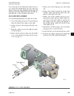
Removing the Compressor Oil
Use the following instructions to remove the compres-
sor oil. Drain the existing oil in the oil separator, which
is under positive pressure at ambient temperature, into
an approved refrigerant recovery container.
1. Connect one end of a refrigeration charging hose
to the service valve located at the bottom of the
oil separator; connect the other end to an ap-
proved container.
2. Open the valve, and drain the
existing
oil from the
oil separator.
3. Additional oil is in the compressor that can
be drained through the plug under the motor
housing.
Summary of Contents for QWC4
Page 14: ...QUANTECH 14 FORM QWC4 NM1 221 ISSUE DATE 02 28 2021 THIS PAGE IS INTENTIONALLY LEFT BLANK...
Page 64: ...QUANTECH 64 FORM QWC4 NM1 221 ISSUE DATE 02 28 2021 THIS PAGE IS INTENTIONALLY LEFT BLANK...
Page 82: ...QUANTECH 82 FORM QWC4 NM1 221 ISSUE DATE 02 28 2021 THIS PAGE IS INTENTIONALLY LEFT BLANK...
Page 130: ...QUANTECH 130 FORM QWC4 NM1 221 ISSUE DATE 02 28 2021 THIS PAGE IS INTENTIONALLY LEFT BLANK...
Page 146: ...QUANTECH 146 FORM QWC4 NM1 221 ISSUE DATE 02 28 2021 THIS PAGE IS INTENTIONALLY LEFT BLANK...
Page 152: ...QUANTECH 152 FORM QWC4 NM1 221 ISSUE DATE 02 28 2021 THIS PAGE IS INTENTIONALLY LEFT BLANK...
Page 155: ...QUANTECH 155 NOTES...