7-14
Field–Replaceable Units (FRUs)
511010 Rev. 07-01-19
7.10.2
Carriage Assembly Replacement
This procedure assumes that the Carriage Assembly was removed in Section 7.7.1.
If the Carriage Assembly is replaced with a different Carriage Assembly, then the li-
brary will require re-calibration. See section 7.17.
1.
Carefully align the Carriage Assembly with the RLS and slowly slide it in mak-
ing sure that the System connector cable clears the 10U Z Satellite PCBA as the
Carriage Assembly slides to the rear of the RLS.
2.
Carefully finish sliding the Carriage Assembly until the two guide pins connect
with their corresponding holes.
3.
Use a No. 2 Phillips screwdriver to replace the two screws that were removed
earlier. See Figure 7-10.
4.
Reach into the RLS to the right side of the Carriage Assembly and carefully re-
connect the System connector to the 10U Z Satellite PCBA.
7.11
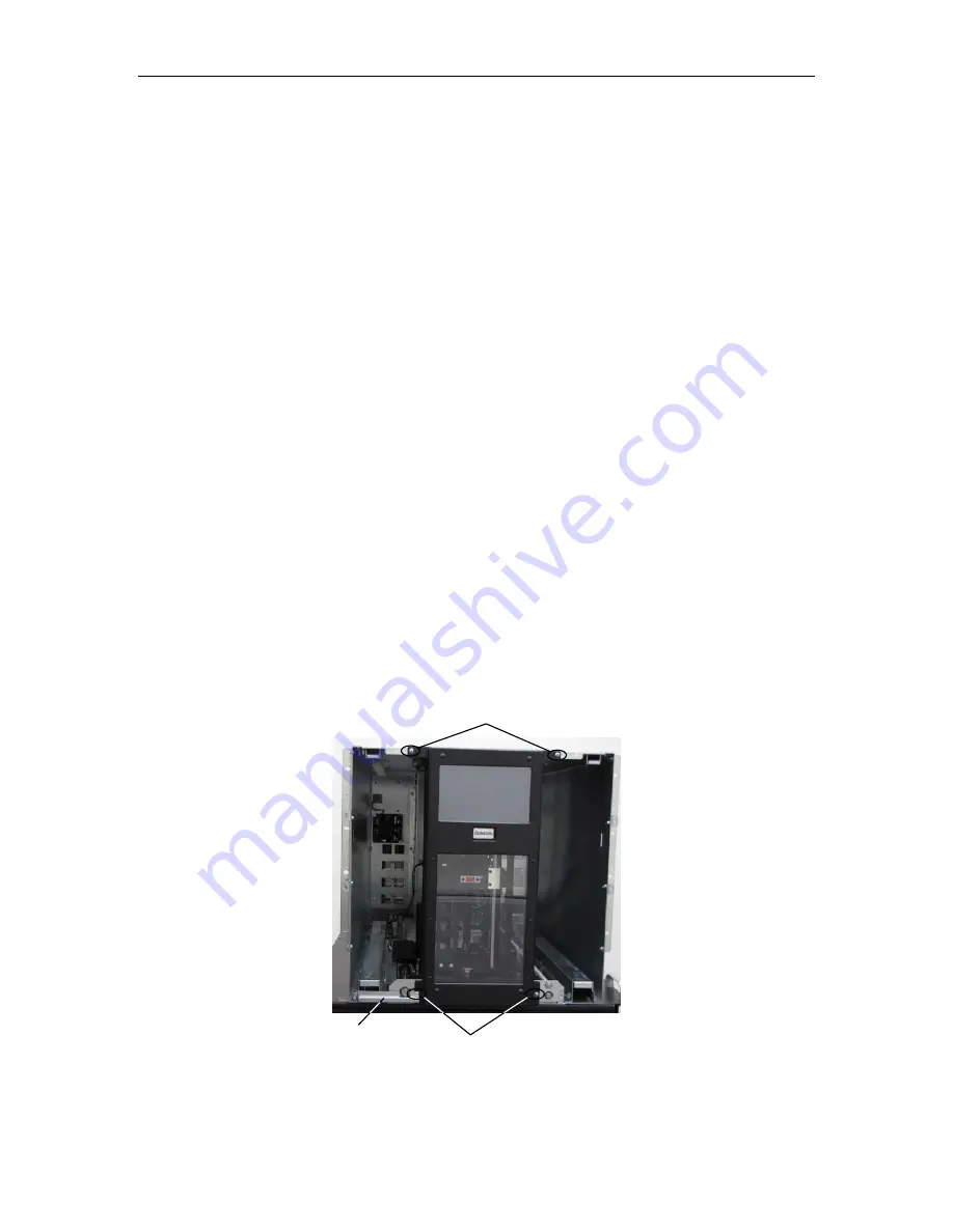
User Interface Panel Assembly
P/N 510752-01-7
RLS-85XX
P/N 510752-02-5
RLS-8350
Tools Required:
•
No. 2 Phillips Screwdriver
Figure 7-11 User Interface Panel Assembly shown with Storage Matrices Removed
Top 2 Screws
Bottom 2 Screws
Sheet Metal
Cable Guard
Summary of Contents for RLS-8350
Page 1: ...RLS 8350 85XX Series Tape Library Technical Service Manual Document No 511010 Rev 07 01 19 ...
Page 2: ......
Page 7: ...511010 Rev 07 01 19 v ...
Page 14: ......
Page 62: ......
Page 64: ......
Page 106: ......


