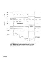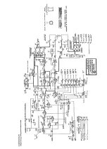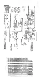
c. If the feedback signals are present, look at each of the following
control signals and compare it with the timing diagram: (The first 4 signals
have logic low and high levels of 0 and +5 V; the last 8 signals, -8 and +5V)
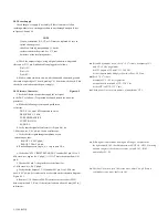
PBST, at U33 pin 10;
PMSR, at U33 pin 12;
PTSW, at U33 pin 8;
RES, at U29 pin 8 (reset, normally only at power turn-on);
SSW1, at U39 pin 5 (from PSSW1, at U33 pin 6);
SSW2, at U39 pin 12 (from PSSW2, at U33 pin 2);
Clock at U34 pin 9 (from 4F, at U29 pin 6);
Reset at U34 pin 1 (from same sources as DONE);
BST, at U40 pin 13 (clocked by 4F, enabled by PBST); BST, at U40 pin 5
(complement of BST);
MSR at U40 pin 6 (clocked by 4F, enabled by PMSR); ISW, at U40 pin 12
(clocked by 4F, enabled byPISW).
If any is abnormal, trace back to the source of the signal, with the help
of the schematic diagram (to check for poor connections or other interface
problems). If the source is faulty, go to para 5.8.6. If these control signals
are all valid, the fault is probably in the integrator U44 or associated
circuits.
5.8.6 Digital Circuitry.
Display Board.
A faulty integrated-circuit package can usually be
identified by interchanging plug-in component parts of the same type
between display channels. Notice that a resistor network need NOT be
replaced as a unit; use ordinary resistors. (See para 5.8.1.)
Recommended Procedure.
If careful analysis of a faulty instrument,
using the preceding information, indicates that the trouble is in the digital
circuitry (whether in control, computation, or display decoding), further
analysis is beyond the scope of this manual. Return the faulty board (the C
board, if the fault is digital, and not
in the display board) or return the instrument for service. Refer to para 5.2
and 5.3.
Special Testing.
Because of the very high speed and considerable
complexity of the C-board digital circuitry,
it is impossible to analyze trouble there with ordinary
test equipment. GenRad production and in-factory
service departments make use of fast, versatile automatic test systems (G R
products). Their efficiency and accuracy are important factors in our
recommendation that
digital circuit problems be solved by exchanging boards.
5-18
SERVICE
Summary of Contents for 1657 RLC Digibridge
Page 6: ...Table of Contents...
Page 8: ...1 2 INTRODUCTION...
Page 9: ...INTRODUCTION 1 3...
Page 10: ...1 4 INTRODUCTION...
Page 15: ...OPERATION 3 1...
Page 24: ...4 2 THEORY...
Page 30: ...5 4 SERVICE...
Page 42: ...5 16 SERVICE...
Page 46: ......
Page 49: ......
Page 50: ......
Page 51: ......
Page 52: ......
Page 53: ......
Page 54: ......
Page 55: ......
Page 56: ......
Page 57: ......

