3.2 CONNECTION OF THE DUT.
3.2.1 The Integral Test Fixture.
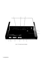
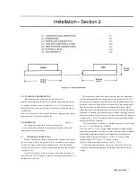
The test fixture provided on the front ledge of the Digi
bridge provides convenient, reliable, guarded 4-terminal connection to
any common radial-lead or axial-lead component.
If the slots of your test fixture have rounded ends, the
slots accommodate wires of any diameter from 0.25 mm (.01 in., AWG
30) to 1 mm (.04 in., AWG 18), spaced from 6 to 98 mm apart (0.23 to 3.9
in.) or equivalent strip conductors. Each "radial" wire must be at least 1 cm
long
(0.4 in.). However, if the slots of your test fixture have square ends, they
will accommodate wires spaced as close as 4 mm (0.16 in.) and each
"radial" wire must be at least
4 mm (0.16 in.) long. The divider between the test slots contains a shield, at
guard potential, with its edges exposed. The adaptors accomm odate wi res
of any diameter up to 1.5 mm (.06 in., AWG 15). The body of the DUT that
will fit between these adaptors can be 80 mm long and 44 mm diameter
(3.1x1.7 in.) maximum. Each "axial" wire must be at least 3 mm long (0.12
in.).
For radial-lead parts, remove each adaptor from the test fixture by a
gentle pull upward, made easier by bending the adaptor left or right (never
forward or back). For axial-lead parts, insert the adaptors, one in the left
slot and the other
in the right slot of the test fixture, by pushing vertically downward. They
can be slid left and right to match the length of DUT to be measured. Notice
that the contacts inside the adaptor are off center; be sure to orient the
adaptors so the contacts are close to the body of the DUT, especially if it
has short or fragile leads.
Insert the DUT so one lead makes connection on the
left side of the test fixture, the other lead on the right side. Insertion and
removal are smooth, easy operations and connections are reliable if leads
are clean and straight.
Be sure to remove any obvious dirt from leads before inserting them.
Be sure the contact pair inside each half of the test fixture is held open by a
single item ONLY, whether that is one lead of an axial-lead DUT or one
adaptor, to obtain true "Kelvin" connections.
3.2.2 Test Fixture Accessories.
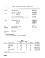
An accessory extender cable or adaptor, cable, and remote test fixture,
as described in Table 1-3, is needed
to connect any DUT that is multiterminal, physically
large, or otherwise unsuited for the built-in test fixture.
A cable is needed, for example, to connect impedance standards, a
remote test fixture, capacitors to be measured with bias, etc. For
connection to the instrument, refer to paragraph 2.5. For
measurements with bias,
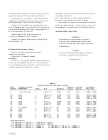
refer to paragraphs 2.6 and 3.6. The color code for the branched end
of each cable is given in paragraph 3.1. To correct for cable
capacitance, refer to paragraph 3.7.
3.3 FUNCTION AND RANGE SELECTIONS.
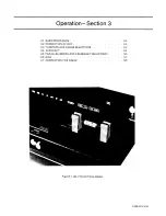
3.3.1 Function Pushbuttons.
The selection of the principal parameter to be measured is almost self-
explanatory. Depress the appropriate FU NCTION button: R, L/Q or C/D to
measure resistance, inductance, or capacitance. The instrument will tolerate,
to some degree, a poor choice of function, but accuracy is thereby reduced.
The readout will indicate a completely wrong choice of function, as
explained below. Notice that the appearance of a device can be misleading.
(For example, a faulty inductor can be essentially capacitive or resistive;
a component part can be mislabeled or unlabeled.)
If both ADJUST RANGE lights are on, the RANGE 2 button is in, the
RLC display is blank, and the DUT is properly connected, then the choice
of function is probably wrong. Most likely, if the L/Q button is in, the DUT
is capacitive; or if the C/D button is in, the DUT is inductive.
Observe the DQ display for an indication of poor choice of function
(though tolerable). Large D or small 0 may indicate that the "reactor" being
measured is practically a
resistor at the measuring frequency. If the C/D
button is in and the D
reading is between 1 and 10 (or blank, as it will be for D> 10) it is
possible that the DUT is eno,ugh like a resistor to be measured best
with the R button in. Similarly, if the L/Q button is in and the Q reading
is
between zero and 1, it is possible that the DUT is enough like a resistor to
be measured best with the R button in. Notice that when the R button is in,
the DO display is always blank. On the other hand, any D or Q display is
valid, even if the "wrong" function has been selected. (The C or L display
can be blank.)
If the R button is in (a resistor is being measured) the easy way to
determine whether the DUT is reactive is to try making C/D and L/Q
measurements. If you obtain a valid C measurement with D < 1, the DUT is
capacitive. The smaller this D value, the less accurate the R measurement.
Similarly, if you obtain a valid L measurement with Q > 1, the DUT is
inductive. The larger this Q value the less accurate the R measurement. (See
para 3.4.)
3.3.2 Range Pushbuttons.
Range selection is also nearly self-explanatory. Follow the ADJUST
RANGE lights. The left light means: "Push the next range button to the
left." The right-hand light
means: "Push the next range button to the right." Continue until both lights
go out. The instrument will usually display a measurement (at reduced
accuracy) even though the range is not optimum. The following details
about range are best
understood with reference to para 3.4 (particu1arly the RLC basic accuracy
graph).
The RANGE buttons are placed in order of decreasing impedance, 3-2-
1. The "highest" range is therefore Range 1
for C/D; but it is Range 3 for Rand L/Q.
OPERATION 3-3
Summary of Contents for 1657 RLC Digibridge
Page 6: ...Table of Contents...
Page 8: ...1 2 INTRODUCTION...
Page 9: ...INTRODUCTION 1 3...
Page 10: ...1 4 INTRODUCTION...
Page 15: ...OPERATION 3 1...
Page 24: ...4 2 THEORY...
Page 30: ...5 4 SERVICE...
Page 42: ...5 16 SERVICE...
Page 46: ......
Page 49: ......
Page 50: ......
Page 51: ......
Page 52: ......
Page 53: ......
Page 54: ......
Page 55: ......
Page 56: ......
Page 57: ......

