


d. Remove the ribbon cable (1657-0200) from power supply (at V-J1)
and main board (at C-J1). Notice that the connectors are symmetrical and
reversible; and the cable is
extra long, for convenience in servicing.
The next step, removal of the power supply, is NOT related to the
removal of the main board. Either can be left in place whi Ie the other is
removed.
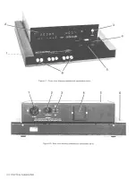
e. Remove the 4 screws that pass vertically through the corners of the
power supply into the main chassis. Lift the power supply slightly and
move it back carefully while disengaging
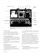
the POWER pushbutton extension from its hole in the front
panel (Figure 5-3). Reassembly note: 4 screws,
8 mm long.
f. After disconnecting the ribbon cable, provide a convenient
"upsidedown" support by reinstalling the top cover, temporarily. Turn the
instrument, bottom up.
g. Remove 4 screws from the bottom shell, one near
each rubber foot. Slide the bottom shell back (or forward), free of the
main chassis (Figure 5-4). Reassembly notes: Be sure to enfold the pliable
dirt seals at left and right sides of main chassis as you start to slide bottom
shell onto main
chassis; use 4 screws, 8 mm long.
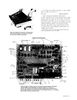
h. Remove 8 screws shown in Figure 5-5 as ABCGHI
(7 mm) and EJ (8 mm). Lift the rear edge of the main board as shown in
Figure 5-6 and slide it back until clear of the main chassis.
i. For access to the test-fixture contacts, which are on the main board,
remove screws K L and drop the test-fixture guide block off of the test
fixture contacts. Refer to bottom interior view, Figure 5-5.
5-8 SERVICE
Notice that it is possible to remove the main board with the display
board mounted on it, by this procedure: release all 8 front push buttons;
remove screws ABCEGHIJ; lift
rear edge of main board 25 mm and slide it forward 16 mm; lift rear edge to
75 mm (so display board clears cutout in main chassis) and slide the
assembly back until display board reaches spacer; lift rear edge another 15
mm and slide it back until push buttons are free; lift assembly out.
Reassembly note: install screw "I," loosely. Position test fixture as
desired (preferably symmetrical in its opening), before installing screws A,
E, etc.
Summary of Contents for 1657 RLC Digibridge
Page 6: ...Table of Contents...
Page 8: ...1 2 INTRODUCTION...
Page 9: ...INTRODUCTION 1 3...
Page 10: ...1 4 INTRODUCTION...
Page 15: ...OPERATION 3 1...
Page 24: ...4 2 THEORY...
Page 30: ...5 4 SERVICE...
Page 42: ...5 16 SERVICE...
Page 46: ......
Page 49: ......
Page 50: ......
Page 51: ......
Page 52: ......
Page 53: ......
Page 54: ......
Page 55: ......
Page 56: ......
Page 57: ......