they will fit the socket directly.) Check at U12 pin 4 for a
1-kHz noisy sine wave, 0.4 V pk-pk. If this is verified but
step g is not, fault is in U18. If neither is verified, reinstall U 18 and
continue.
i. Check that each input to the D/A converter U12 (pins 5. ..12), is a
digital signal, about 4 V pk-pk. Each
of these 8 signals should repeat with a period of 1 ms.
If these digital signals are NOT correct, continue the analysis by
checking the crystal oscillator and divider chain, as follows.
NOTE
Dual specifications of frequency appear below.
The first frequency is correct for 1657-9700
(the 120-H z version). The second is correct
for 1657-9800 (the 100-Hz version). Frequency tolerance is +/-0.01%
j. Make the following test setup. Connect from the scope vertical-
channel output to a counter. Be sure to use a lowcapacitance probe at the
scope input, so as not to load the high-impedance circuits being analyzed.
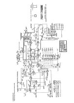
k. Oscillator. Check at U8 pin 14 for a fast digital waveform (see
schematic diagram) of the following frequency: 25.067 or 24.576 :1:0.003
MHz. If correct,
skip to step 1. (This circuit is easily loaded down by test equipment. A more
"tolerant" point is checked in step I.)
l. Check at U8 pin 8 for a square wave, 4 V pk-pk,
2.0889 or 2.0480 MHz. Otherwise, U8 is faulty.
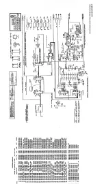
m. Check at U9, pins 1, 9, 8 for pulses (essentially rectangular, as shown
on the schematic diagram), with frequencies as follows:
Pin 1, 1.0445 or 1.0240 MHz.
Pin 9, 522.24 or 512.00 kHz.
Pin 8, 261.12 or 256.00 kHz.
Otherwise, U9 is faulty.
n. Check at U10, pins 12,9,5 for similar pulses, as
shown, with frequencies as follows:
Pin 12, 276. or261.12 kHz.
Pin 9, 61.440 or 78.3 kHz.
Pin 5, 30.720 or 26.112 kHz.
Otherwise, U10 is faulty.
NOTE
At pin 12, for the 1657-9700, every 9th square
wave is half the regular width; at pin 9, for
the 1657-9800, every 3rd positive pulse is
only about 1 us wide; therefore the counter
reading may vary somewhat, depending on the
length of its counting interval.
o. Check at U14 pin 2 for square waves, 5 V pk-pk, at 261.12 or 256.00
kHz.
ia.
If these inputs are verified but step h is not, fault is in
U12 circuit Check at the end of R
16
closest to the rear corner
for
+3
V dc; if that is correct, replace U
12.
Otherwise, fault
is in associated circuit
k
.
a
. If oscillator signal is not verified, remove U8 from its
socket and repeat step k. (Check at U13 pin
13,
if convenient.) If
signal is now normal, U8 is faulty. Otherwise, install U8 and
determine whether your instrument has a self-contained oscillator
or a separate crystal Y1.
kb
. If your instrument has a separate crystal, remove it and
repeat step k. The correct frequency is approx
31.2
MHz (either 120- or 100-Hz version). If this is verified, Y1 is
faulty. Otherwise, install Y1 and check at U7 pins
2, 3, 11
for
voltages of
+4, +3,
+4.2V, respectively. If they are correct, U7 is
faulty.
kc
. If your instrument has the self-contained
oscillator, failure in steps k and ka indicates the oscillator U7 is
faulty.
oa
. lf step
0
is no t confirmed, be sure you have selected
1
kHz on the front panel. Check that FREO SEL (U15 pin
8)
is
logic high and FREO SEL (pin
6)
is low. (Otherwise check back
through U24, U19, andS8.)
ob
. If those checks are confirmed, fault is in the gates U15
pins
4,
10,3 or U14 pin
2.
SERVICE 5-13
Summary of Contents for 1657 RLC Digibridge
Page 6: ...Table of Contents...
Page 8: ...1 2 INTRODUCTION...
Page 9: ...INTRODUCTION 1 3...
Page 10: ...1 4 INTRODUCTION...
Page 15: ...OPERATION 3 1...
Page 24: ...4 2 THEORY...
Page 30: ...5 4 SERVICE...
Page 42: ...5 16 SERVICE...
Page 46: ......
Page 49: ......
Page 50: ......
Page 51: ......
Page 52: ......
Page 53: ......
Page 54: ......
Page 55: ......
Page 56: ......
Page 57: ......


