5.6.3 Reference Designations.
Refer to Section 6 for an explanation of these designations.
For example, V- T1 designates transformer number one in the
power supply (V) assembly. C-U3 is integrated circuit number 3 on the
C board, which is the analog and control board or the main board.
5.6.4 Removal of Multiple-Pin Packages.
Use caution when removing a plug-in integrated-circuit or other
multiple-pin part, not to bend pins nor stress the circu it board. Withdraw
the part straight away from the board. Unless an IC is known NOT to be a
MaS type, place it immediately on a conductive pad (pins in the pad) or
into a conductive envelope.
Do NOT attempt to remove a soldered-in IC package without the
proper equipment and skills to do so without damage. If in doubt, return
the board to Gen Rad.
5.7 PERIODIC MAINTENANCE.
5.7.1 Care of the Test Fixture.
About once a year (more or less depending on usage) the
test fixture should be inspected and cleaned as follows:
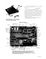
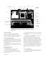
a. Remove the C board and expose the text-fixture contacts by
removing its guide block (part number 1657-2200), as described above.
See Figure 5-5, screws KL.
5-10 SERVICE
b. Clean and check the 4 contact strips. Use a card wet with isopropyl
alcohol for cleaning. Hold the board at an angle so that any drip falls away
from the circuits.
c. If necessary, the contact strips (part number 16861940) can be
removed (2 screws apiece). They are supposed
to press against each other, with tiny dielectric spacers preventing
contact. Except at the ends of the gap (where the spacers are) the gap
should be .05 to 0.2 mm (.002 to .008 in.) all along the gap. If accurate
feeler gages are not available, the following criterion can be used: the gap
shou Id be large enough to pass a strip of ordinary typing paper without
dragging, but narrow enough everywhere (at center and near each end) to
cause some drag as a stack of 3 strips of paper is passed through.
For best results and minimum maintenance effort, the operator must
remove any obvious dirt from leads of DUT's before inserting them into the
test fixture. Its contacts will wipe through a film of wax, but they can
become clogged and ineffectual if the operator is careless about cleanl
iness.
5.7.2 Care of the Display Panel.
Use caution when cleaning the display vyindow, not to scratch it nor to
get cleaning substances into the instrument. Use soft cloth or a ball of
absorbent cotton, moistened with
Summary of Contents for 1657 RLC Digibridge
Page 6: ...Table of Contents...
Page 8: ...1 2 INTRODUCTION...
Page 9: ...INTRODUCTION 1 3...
Page 10: ...1 4 INTRODUCTION...
Page 15: ...OPERATION 3 1...
Page 24: ...4 2 THEORY...
Page 30: ...5 4 SERVICE...
Page 42: ...5 16 SERVICE...
Page 46: ......
Page 49: ......
Page 50: ......
Page 51: ......
Page 52: ......
Page 53: ......
Page 54: ......
Page 55: ......
Page 56: ......
Page 57: ......

