Insignificant figures.
The right-hand digit(s) of the display normally flicker
and change if they are not significant for the specified accuracy of the
instrument. Refer to
para 3.4.
Series DUT.
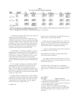
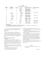
For check number 17 of Table 5.2, the SUT is a series
connection of 0.033 uF and 499
Ω
for check 18, 0.033 uF and 49.9
Ω
.
For these checks, remove the adaptors from the test fixture. Insert the resistor
in one side and the capacitor in the other side, both slanted so their upper
leads cross each other. Clamp them together with a small alligator clip or
paper clip.
5.5 MINIMUM PERFORMANCE STANDARDS.
5.5.1 General.
This procedure is a more rigorous alternative to the performance
verification described above. Precision stan. dards of impedance are required
for this procedure, which checks the accuracy as well as the overall
performance of the instrument. It will be controlled from the front panel, without
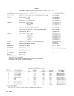
disassembly. Table 5.3 lists the recommended standards and associated
equipment.
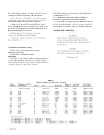
Verify that the instrument meets performance specifications as follows.
Notice that the specifications in the front of this manual supercede any that are
tabulated below.
Calibration of Standard.
The acceptable RLC readout
(min to max range) may have to be modified if your actual
Zx or Zx accuracy is different from the value tabulated.
For example, if your 1-k
Ω
standard is actually 1.005 k
Ω
, known to +/-0.1 %,
then the acceptable readout is 1.005 +/-0.3%, i.e., 1.0020 (min) to 1.0080 (max)
k
Ω
. (Refer to check E of Table 5-4.)
Insignificant Digits.
The right-hand digit(s) of the display normally may
flicker and change if they are not significant for the specified accuracy of the
instrument. Refer to para 3.4.
Cable Capacitance.
Because the cable adds capacitance in parallel with
the OUT, it is sometimes necessary to obtain a "corrected readout" from the
numerical display on the instrument. Do this for all checks involving small
capacitance (about 1000 pF or less). The equivalent correction for large
inductance (above 30 H at 1 kHz or 3000 H at 120 Hz) is not applicable in the
recommended .inductance check procedure. For capacitance measurement,
obtain the corrected readout by subtracting the cable capacitance from the
visible readout, as described in
para 3.7. Because C is large compared to cable capacitance and D is small, the
simple calculation (subtraction) is applicable whether the measurement is
"parallel" or "series."
CAUTION
Be sure the line voltage switch, rear panel, is correctly set for your
power line voltage.
SERVICE 5-3
Summary of Contents for 1657 RLC Digibridge
Page 6: ...Table of Contents...
Page 8: ...1 2 INTRODUCTION...
Page 9: ...INTRODUCTION 1 3...
Page 10: ...1 4 INTRODUCTION...
Page 15: ...OPERATION 3 1...
Page 24: ...4 2 THEORY...
Page 30: ...5 4 SERVICE...
Page 42: ...5 16 SERVICE...
Page 46: ......
Page 49: ......
Page 50: ......
Page 51: ......
Page 52: ......
Page 53: ......
Page 54: ......
Page 55: ......
Page 56: ......
Page 57: ......

