QSK USKI-5 Instructions Manual Download Page 17

USKI-5 Universal Sequencer & Keying Interface 


© Copyright 2015 QSK, llc 

www.qskllc.com 

Page 16 


zero. Assuming the T/R switch and amplifier relays require 15 ms to switch, that amount of time 
is accounted for in the sum of the VFO and transmitter start time. This allows the VFO time to 
start before the transmitter (modern DDS VFOs are generally so fast that no delay is necessary 
after  starting  before  keying  the  transmitter).  Again,  as  in  previous  examples,  end  delay 

5

  is 

equal to the sum of the start delays so that the CW weighting of the transmitted signal correct 
(intentional changes if weighting can be also be accomplished by proper choices of delays). End 
delay 

4

  is  set  to  5  ms  to  allow  the  transmitter  time  to  complete  each  CW  symbol  envelope 

before turning off the VFO. If the VFO turns off its RF output quickly, the RX mute end delay can 
be set to zero. If not, and sometimes for cleaner sounding QSK operation, sometimes a few ms 
delay in the RX mute end delay may be necessary.  

USING LONGER DELAYS 

To minimize timing errors, the microcontroller is overclocked to the maximum frequency allowed 
(32 MHz) in programs (A), (B), and (C). For the programs 

as written, every delay or “pause” is 

limited  to  a  maximum  of  8191  ms.  If  longer  delays  are  desired,  up  to  65535  ms,  the 
microcontroller can be set to operate at its default frequency (4 MHz) by “commenting out” the 
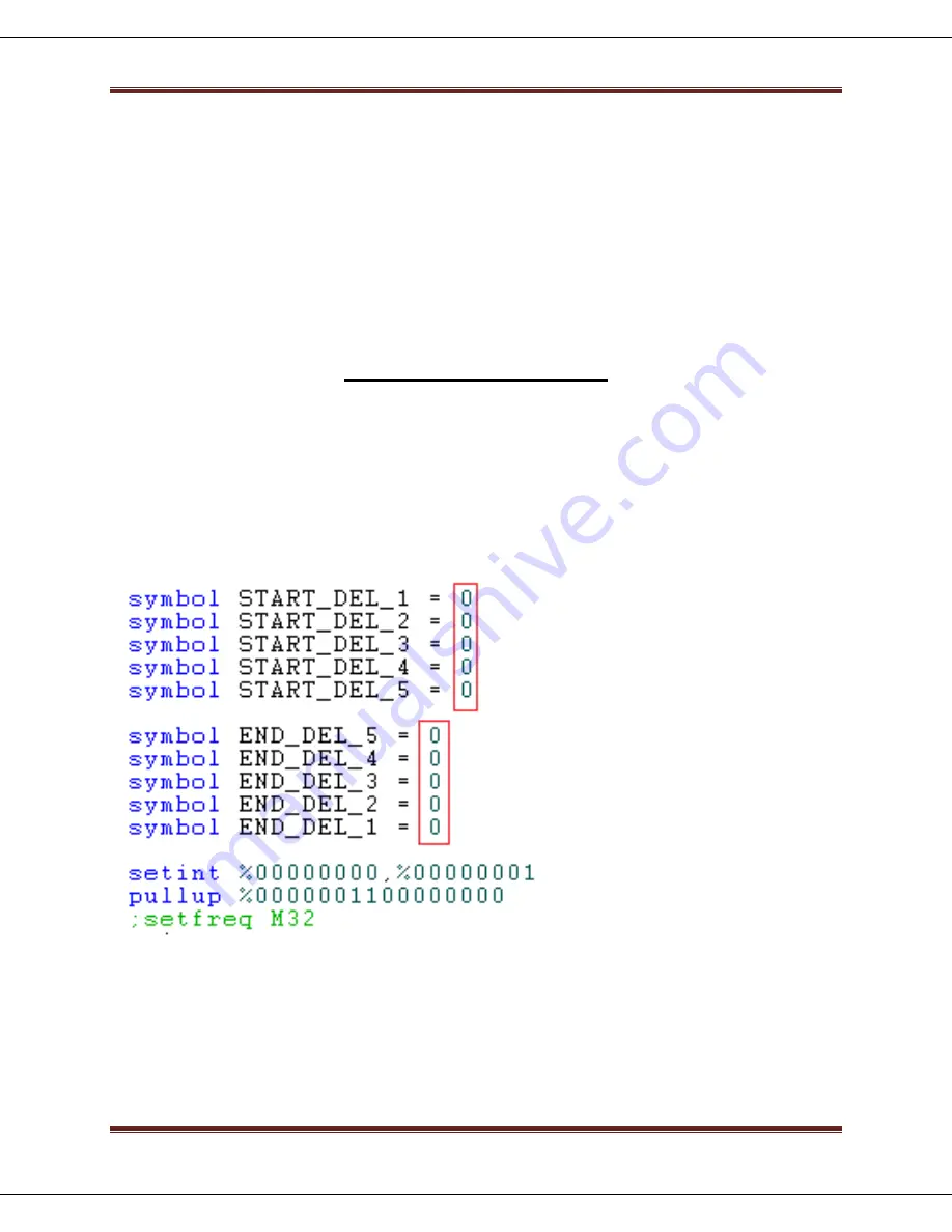
command  line  that  sets  the  clock  frequency  to  32  MHz.  This  is  done  by  simply  adding  a 
semicolon in front of t

he line with the “setfreq m32” command. The START-DEL and END_DEL 

lines should also have the “8 *” removed as shown here: 


If even longer delays are required, refer to the PICAXE© programming manual. 


Summary of Contents for USKI-5

Page 1: ...QSK llc USKI 5 Universal Sequencer and Keying Interface Rev D...

Page 2: ...bit capability Non volatile memory Five output channels four input control channels Delays programmable from zero to minutes and more in 1 ms steps Silent high speed opto isolated solid state relay co...

Page 3: ...r inverted normally closed operation Once programmed the USKI 5 can be operated with or without connection to the programming computer The stored program is nonvolatile and no backup batteries are req...

Page 4: ...ter begins the attack portion of a symbol and must remain on until after decay is complete This same principal also applies to any power amplifier or antenna switching that may occur along with transm...

Page 5: ...upt is activated transmitting will be inhibited regardless of the state of other inputs If the program has already begun the transmitting sequence an interrupt condition will cause the program to imme...

Page 6: ..._3 the program will immediately switch off OUTPUT 3 disregarding the time remaining of TX_START_DEL_3 and will continue by switching off OUTPUT 2 and 1 in sequence with delays TX_END_DEL_2 and TX_END_...

Page 7: ...nction Several station configurations are suitable for control with Program C Probably the most common is shown in figure 3 the order of connections for outputs 1 4 may be different depending on the s...

Page 8: ...me to be on the safe side The user is responsible for correct programming and use of the USKI 5 sequencer During normal receive transmit receive sequencing the transmitter will be the last device to b...

Page 9: ...operation up to 50 WPM the sum of START and END delays must be less than 24 ms USKI 5 PREPARATION FOR USE The USKI 5 is shipped without the output relays installed Remove the four 1 Pozidriv screws a...

Page 10: ...t File Save As and add the extension bas to the file name as indicated below and then select Save The file will be saved with the proper extension Connect the sequencer to the computer with the USB ca...

Page 11: ...e called CW_START_DEL PTT_START_DEL or TX_START_DEL for example It may be helpful to first fill out a timing delay work sheet shown in the notes section at the end of this document Change the START an...

Page 12: ...gram they may include cwstart cwend pttstart pttend txstart or txstend routines For any inverted channel change high to low in the start routines of the program and low to high in the end routines of...

Page 13: ...g input devices connected to the sequencer and without the outputs connected to the station equipment Once the correct relative sequencing has been confirmed the sequencer can be reprogrammed with the...

Page 14: ...g delays Remember that for Programs A B or C the sequence will progress from left to right for the start delays and from the right to the left for the end delays For the output connections shown in pr...

Page 15: ...t to be on the safe side it is the first device switched off or out of circuit In this example it is assumed that there are mechanical relays which do this switching and transition in 10 ms In case th...

Page 16: ...CW mode particularly QSK operation Since transmitter PTT is not connected to the sequencer this allows for up to five other external devices to be controlled This example is for a station with separat...

Page 17: ...ch CW symbol envelope before turning off the VFO If the VFO turns off its RF output quickly the RX mute end delay can be set to zero If not and sometimes for cleaner sounding QSK operation sometimes a...

Page 18: ...RING 5 C 2 OUTPUTS OUTPUT NUMBER 14M2 PIN NUMBER PIN PROGRAM DESIGNATION 1 12 B 1 2 11 B 2 3 10 B 3 4 9 B 4 5 8 B 5 USEFUL INFORMATION Enhanced switching capabilities over what is possible with the st...

Reviews: