


Page 8 of 16 ft8_II_assy_smd_diode_072020.pdf
Note: When reading module capacitor values, do not confuse the manufacturing
codes with the component value. If it looks strange, it may be a manufacturing
code, look on the other side of the component.
Be sure you have read the values correctly. Sort all the capacitors out before
you start assembling them onto the modules. They are difficult to remove and
correct.
L1 molded inductors look like a resistors, but are fatter. With an ohm meter, will read 0 ohms.
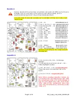
40M
[ ] L1 – 2.2 uH – Red/Red/Gold/Gold or Red/Red/Gold/Silver
[ ] C26 – 100 pfd – marked 101
[ ] C27 – 22 pfd – marked 22 or 220
[ ] C28 – 22 pfd – marked 22 or 220
[ ] C29 – 330 pfd – marked 331
[ ] C30 – 680 pfd – marked 681
[ ] C31 – 68 pfd – marked 68 or 680 (don't mix up the 681 and 68 values!)
[ ] C32 – 330 pfd – marked 331
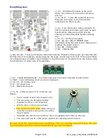
[ ] L2 – 20 turns on T37-2 RED core – make sure turns are snug to the core and more or less
evenly spaced around the core. Loose winding does not work well.
[ ] L3 – 18 turns on T37-2 RED core
[ ] X1 – 7.074 MHz crystal. If you are
not
using the optional VFO, you need to jumper the
“CRYSTAL ENABLE” pads with a clipped piece of a resistor lead. Otherwise
omit
the jumper for
VFO operation.
30M
[ ] L1 – 1.2 uH – Brown/Red/Gold/Gold or Brown/Red/Gold/Silver
[ ] C26 – 100 pfd – marked 101
[ ] C27 – 22 pfd – marked 22 or 220
[ ] C28 – 22 pfd – marked 22 or 220
[ ] C29 – 220 pfd – marked 221
[ ] C30 – 560 pfd – marked 561
[ ] C31 – 47 pfd – marked 47 or 470
[ ] C32 – 220 pfd – marked 221
[ ] L2 – 18 turns on T37-2 RED core – make sure turns are snug to the core and more or less
evenly spaced around the core. Loose winding does not work well.
[ ] L3 – 13 turns on T37-2 RED core
[ ] X1 – 10.136 MHz crystal. If you are
not
using the optional VFO, you need to jumper the
“CRYSTAL ENABLE” pads with a clipped piece of a resistor lead. Otherwise
omit
the jumper for
VFO operation.