


Page 7 of 16 ft8_II_assy_smd_diode_072020.pdf
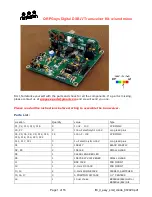
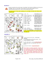
Special Note:
Do not proceed until you make this check.
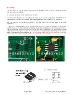
If you have installed T1 correctly, you should read
0 ohms with an ohm meter between the two pads marked by the red arrows on T1. If you have
installed T2 correctly, you should read 0 ohms with an ohm meter between the two pads marked
by the blue arrows on T2. If not, investigate and correct before going any further.
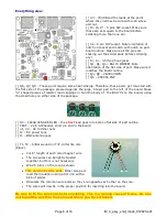
[ ] Stick the rubber bumper feet on the bottom of the board.
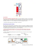
Assembling the band modules:
We supply three band modules and detailed the values for 20/30/40m. Additional bare band
module pcb’s are available for operation on other bands. At the end of this document we have
modeled additional band component values. They are starting points; tweaking of the values may
be necessary, and you will need to source your own components.
[ ] Before populating with components,
mark each module with the band in the space
provided with a permanent marker
.
They can easily get mixed up during assembly and
difficult to correct.
[ ] J5,J6 – 5 pin right angle SIP header strip. Short 90° pins go into board. Mount on the top of
the board as shown.
Use the placement graphic and tables below to install the capacitors, crystals, and inductors.