


Page 5 of 16 ft8_II_assy_smd_diode_072020.pdf
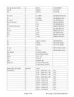
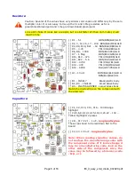
Resistors:
Caution: Several of the values have very similar color codes and differ only by the zero
multiplier color. It is also easy to mix up the 51 and 1 Meg resistors as 51 is
green/black/brown/gold and 1 meg is brown/black/green/gold.
L4 is a RF choke. It looks like a resistor, but is a bit fatter. With an ohm meter, it will
read 0 ohms.
[ ] R1 - 51
GRN/BRN/BLK/GLD
[ ] R2, 3, 12, 16, 17 – 10K BRN/BLK/ORG/GLD
[ ] R4, R9, R18, R21 - 1K BRN/BLK/RED/GLD
[ ] R5 - 4.7K
YEL/VOL/RED/GLD
[ ] R6, R8 - 100K BRN/BLK/YEL/GLD
[ ] R7 - 1 Meg
BRN/BLK/GRN/GLD
[ ] R10, R19 - 470 YEL/VOL/BRN/GLD
[ ] R11, R20 - 5.6 GRN/BLU/GLD/GLD
[ ] R13 – 470K
YEL/VOL/YEL/GLD
[ ] R14 – 47K
YEL/VOL/ORG/GLD
[ ] R15 – 680K
BLU/GRY/YEL/GLD
[ ] L4 – 10 uH
BRN/BLK/BLK/GLD or
BRN/BLK/BLK/SIL
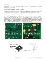
[ ] D1 – 1N5817 Black plastic body
[ ] D2, D3 – 1N4148 Small Glass body
[ ] D5 – 1N4756A ZENER Larger Glass body
Match the diode stripe on the component with
the silkscreen
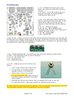
Capacitors:
[ ] C1, C2, C10, C13, C16 – 103 Orange
highlight
[ ] C4,5,6,8,9,12,14,15,18,19,20,22 – 104 –
Yellow highlight 12 places
[ ] C11, C17, C21 – 1 uF –
long lead is plus.
These caps need to be laid down flat to the
board.
[ ] C3, C7- 100 uF –
long lead is plus.
Note: When reading capacitor values, do
not confuse the manufacturing codes with
the component value. If it looks strange it
may be a manufacturing code, look on the
other side of the component. Also, the
value may be followed by a tolerance code
- M,K, or J.