SYSTEM TESTS
QOLSYS CONFIDENTIAL AND PROPRIETARY
PAGE OF
116
173
SENSOR TEST
(For North American Market Only - Not functional for CE/EN Grade 2)
FIND IT
SYSTEM TESTS
Swipe down
for access
SETTINGS
ADVANCED SETTINGS
ENTER CODE (1111, 2222)
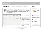
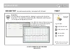
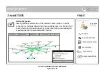
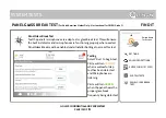
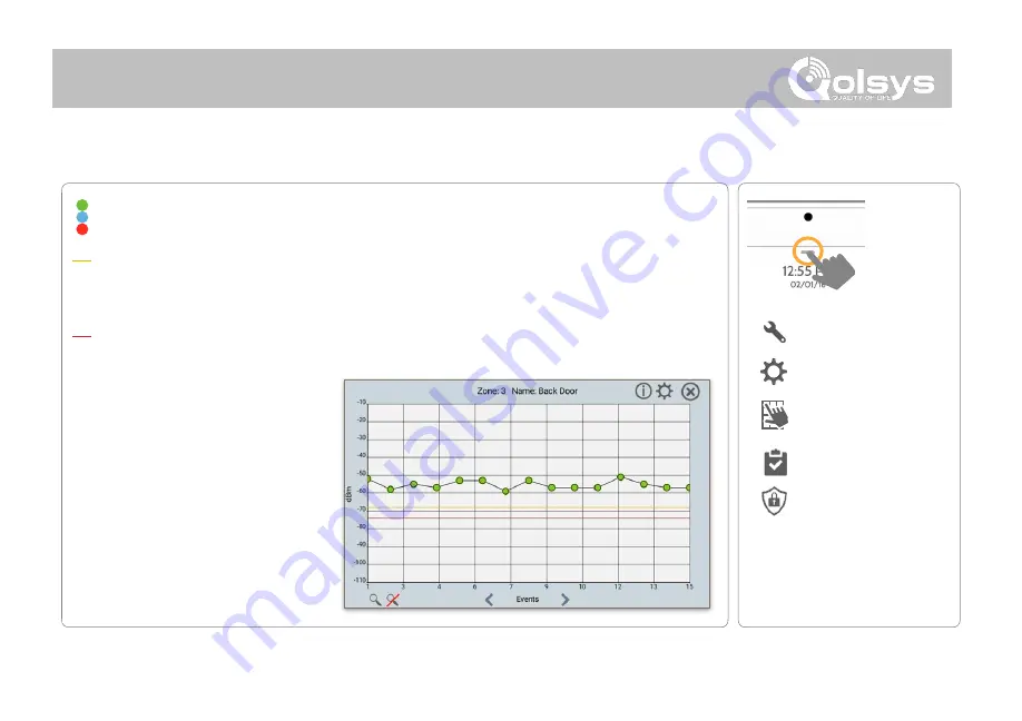
Colored points on the graph represent each state change or supervisory signal
transmitted from a sensor to the panel. Points are colored based on frequency.
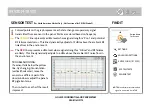
The
YELLOW
line represents a dBm level where signal strength is “Poor” and potential
RF failures could occur. This line dynamically adjusts to 12 dBm above the ambient RF
noise floor in the environment.
The
RED
line represents a dBm level where signal strength is “Critical” and RF failures
are likely. This line dynamically adjusts to 6 dBm above the ambient RF noise floor in
the environment.
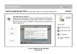
TROUBLESHOOTING:
If a sensor falls below the yellow
line, try changing it’s orientation
(vertical/horizontal), move the
sensor to a different part of the
door/window or adjust the panel’s
RF pigtail antenna.
Then re-test to see the if the result
improved.
SENSOR TEST
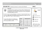
NOTE:
Manufacturer recommended
signal to noise ratio is min 7dB
Summary of Contents for Panel 2+
Page 8: ...INSTALLING THE PANEL...
Page 13: ...USER INTERFACE...
Page 17: ...PROGRAMMING...
Page 52: ...SECURITY SENSORS...
Page 84: ...WI FI DEVICES...
Page 91: ...Z WAVE DEVICES...
Page 102: ...BLUETOOTH DEVICES...
Page 110: ...SYSTEM TESTS...
Page 134: ...CUSTOMIZATION...
Page 147: ...MAINTENANCE...
Page 153: ...TROUBLESHOOTING...
Page 163: ...LEGAL...
Page 169: ...SPECIFICATIONS...


