C
ABLING
D
IAGRAM
C
ABLING
D
IAGRAM
3-1
3.1
Cabling Diagram
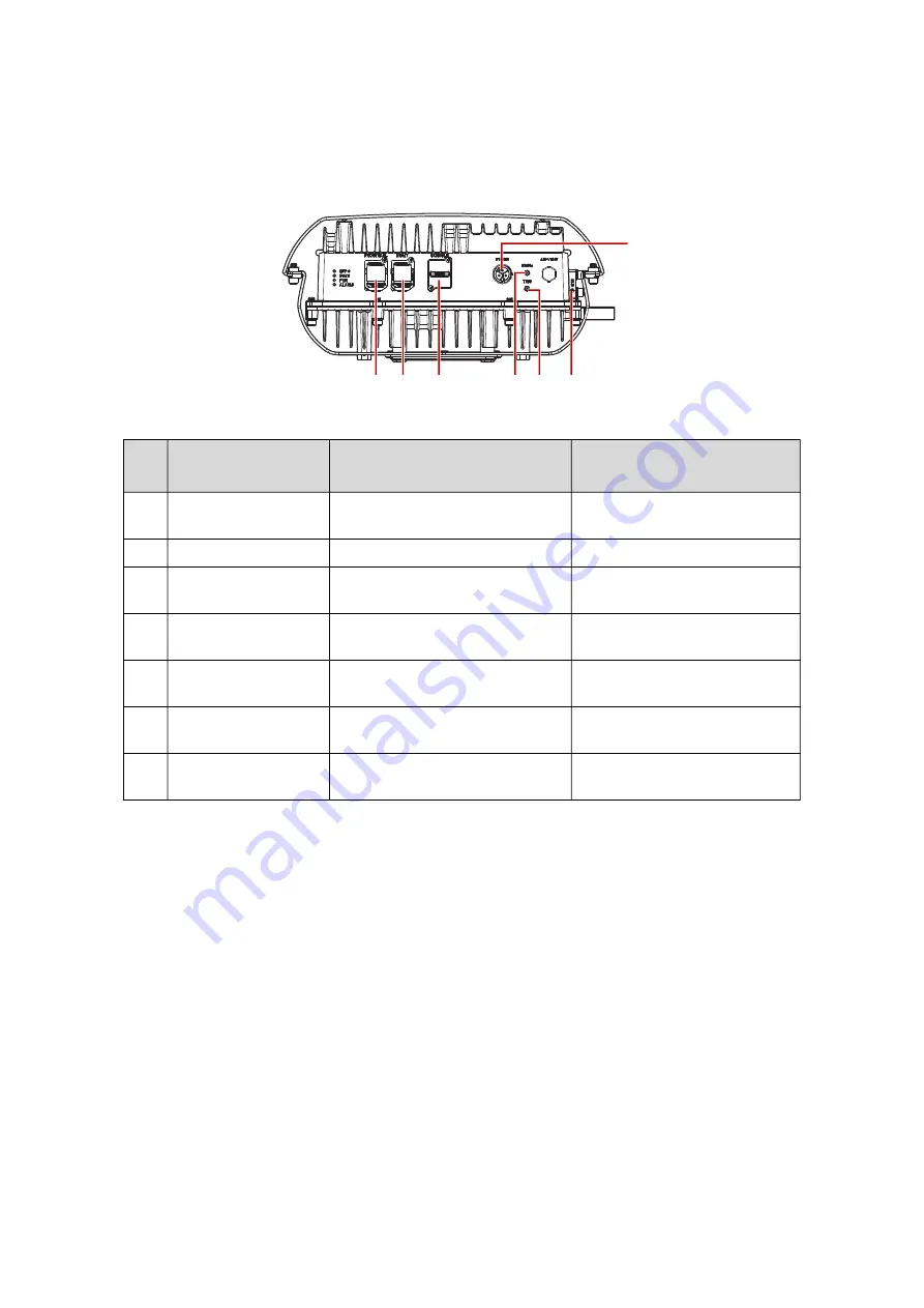
See the following figure and table for information on cable connections.
Figure 3-1.
Front I/O Cable Diagram
*Unavailable for normal operations. For debugging by manufacturer only.
N
O
.
I/O N
AME
D
ESCRIPTION
C
ABLE
S
PECIFICATIONS
(S
HIPPING
E
XCLUDING
)
1.
SFP+ port for FHGW
Fiber cable support FHGW to RRU
up to 2 KM
Waterproof fiber cable is required
for outdoor deployment
2.
Management port*
N/A
N/A
3.
Console port (RJ45)*
Waterproof dummy is provided in
shipping.
N/A
4.
10MHz*
Waterproof treatment, required on
10MHz port to avoid rust
No cable connection required
5.
TRIG*
Waterproof treatment is required
on TRIG port to avoid rust
No cable connection required
6.
GND
Connection point for grounding
the device
Ground cable with 16 AWG
7.
Power port
Connection point for supplying
power to the device
Power cord supports up to 100M
(110/220 AC in, OD: 9.3 mm)
1 2
3
5 6
7
4


