background image


28 aprile 2021 


3.2


Technical data 

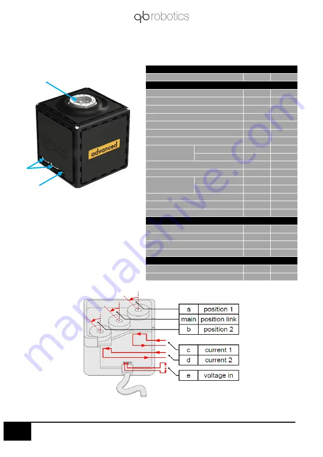
Mechanical and electrical characteristics of the qbmove Advanced: 


Figure 3-2 qbmove Advanced. 

 output 

shaft; 

daisy-chain RS485; 

 USB port. 


operating data 

(quantity) 

(unit) 

(value) 

mechanical 

Continuous Output Power 

[W] 

33 

Nominal Torque 

[Nm] 

5.5 

Nominal Speed 

[rad/s] 

5.5 

Peak Torque 

[Nm] 

6.8 

Maximum Speed 

[rad/s] 

6.33 

Maximum Stiffness 

[Nm/rad] 

83.5 

Minimum Stiffness 

[Nm/rad] 

0.5 

Nominal Stiffness 

Variation Time 

no load 

[s] 

0.25 

max torque 

[s] 

0.25 

Maximum Elastic Energy 

[J] 

0.88 

Maximum Hysteresis 

[°] 

Maximum Deflection 

Max stiffness 

[°] 

Min stiffness 

[°] 

50 

Active Rotation Angle 

[°] 

±180 

Angular Resolution


[°] 

360/32768 

Weight 

[kg] 

0.45 

Electrical 

Voltage Supply 

[V] 

24 

Nominal Current 

[A] 

1.8 

Maximum Current 

[A] 

Peak Current


[A] 

13 

control data 

Nominal current (USB) 

[A] 

0.26 

Electrical protocol 

RS485/USB 


Figure 3-3 Sensors references. 


③ 


Summary of Contents for qbmove Advanced Kit

Page 1: ...Please read these instructions before use Do not discard keep for future reference User manual KIT ...

Page 2: ...www qbrobotics com ...

Page 3: ... robots with natural motion i e that resembles the elegance and deftness of human motion a radical contrast to the traditional rigid and mechanical motion of robots built with common servo mechanisms The qbmove can be tuned to be soft or rigid depending on the task at hand If the robot needs to guarantee safety during impact the actuator can be set to be soft While if precision is the greater need...

Page 4: ...Qbally 16 4 Mechanical assembly 18 4 1 Flat Flange assembly 20 4 1 1 Assembly sequence 21 4 1 2 ERNI cable routing in the Flat Flange 23 4 2 Base Flange assembly 24 4 2 1 Assembly sequence 25 4 3 C Flange assembly 26 4 3 1 Assembly sequence 27 4 3 2 ERNI cable routing in the C Flange 30 4 4 Double Flat Flange assembly 31 4 4 1 Assembly sequence 32 4 5 Gripper assembly 34 4 5 1 Assembly sequence 35...

Page 5: ...1 6 3 3 Delta robot example 68 6 4 qbAPI software protocol 69 6 4 1 Compiler Installation 69 6 4 2 Integrating the functions 70 6 4 3 Basic Functions 70 6 4 4 Code Examples 72 6 5 ROS 76 6 5 1 Installation 77 6 5 2 Usage 78 6 5 3 Delta robot and open kinematic chains examples 86 6 5 4 qb control 91 6 5 5 ROS packages overview 93 7 Troubleshooting 95 7 1 qbmove output shaft doesn t move smoothly 96...

Page 6: ...3 28 aprile 2021 8 Commissioning and Maintenance 99 8 1 Commissioning 100 8 2 Maintenance and warranty 100 9 Appendix 101 9 1 VSA papers 101 9 2 qbmove papers 102 10 Record of documented revisions 103 ...

Page 7: ...liability for actual use based on the examples and diagrams No patent liability is assumed by qbrobotics s r l with respect to use of information circuits equipment or software described in this manual Reproduction of the contents of this manual in whole or in part without written permission of qbrobotics s r l is prohibited 1 1 Using this document The documentation must always be complete and in ...

Page 8: ...se outlet It may cause fire or damage to people Do not use if damaged or defective Do not disassemble the actuators Do not insert any objects between moving parts Do not place your face too close to the robot Disconnect the power supply before cleaning or maintenance Disrespect of these precautions can affect safety of the device 2 2 Environmental conditions Select the installation location so tha...

Page 9: ... can normally be expected from electric miniature drivers Therefore the Machinery Directive does not apply to our products The products described here are not incomplete machines so installation instructions are not normally issued by qbrobotics Low Voltage Directive 2014 35 EU The Low Voltage Directive applies for all electrical equipment with a nominal voltage of 75 to 1500 V DC and 50 to 1000 V...

Page 10: ...3 Introduction to qbmove kit This chapter shows what the qbmove kit includes all the technical information about the qbmove Advanced and its mechanical connection Following the electrical connections between the devices ...

Page 11: ...d of flange Flat Flange n 8 screws M2x8 ISO1207 n 4 nuts M3 ISO4032 A2 n 4 screws M3x8 ISO4762 Base Flange n 8 screws M2x8 ISO1207 n 4 nuts M3 ISO4032 A2 n 3 screws M3x10 ISO10642 C Flange n 16 screws M2x8 ISO1207 Other components n 8 screw M3x10 ISO4762 n 8 nuts M3 ISO4032 A2 Make sure that the following items are included in the package If there are any items missing contact the supplier x 4 x 2...

Page 12: ...ximum Speed rad s 6 33 Maximum Stiffness Nm rad 83 5 Minimum Stiffness Nm rad 0 5 Nominal Stiffness Variation Time no load s 0 25 max torque s 0 25 Maximum Elastic Energy J 0 88 Maximum Hysteresis 5 Maximum Deflection Max stiffness 6 Min stiffness 50 Active Rotation Angle 180 Angular Resolution 360 32768 Weight kg 0 45 Electrical Voltage Supply V 24 Nominal Current A 1 8 Maximum Current A 3 Peak C...

Page 13: ...ensor c Motor 1 Current Resolution A 5 1638 Range A 5 Sensor d Motor 2 Current Resolution A 5 1638 Range A 5 Sensor e Input Voltage Resolution V 25 1638 Range V 0 25 Figure 3 4 qbmove Advanced dimensions The qbmove is a back drivable actuator When the robot is off a sufficiently high external load can move the output shaft Do not use the Peak torque more than few seconds ...

Page 14: ...11 28 aprile 2021 Dimensions of the flanges Figure 3 5 C Flange dimensions Figure 3 6 Base flange dimensions ...

Page 15: ...12 28 aprile 2021 Figure 3 7 Snap on mechanism Figure 3 8 Examples of connection ...

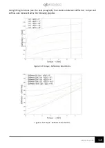
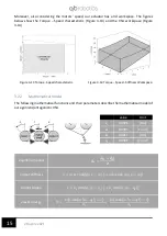
Page 16: ... the motors positions q1 and q2 on the torque τ and on the mathematical model of the system Figure 3 9 Agonist Antagonistic VSA model All these quantities are each other connected then to evaluate a proper mathematical model experimental data are needed Using a pendulum structure a sinusoidal movement with different frequencies and different stiffness presets the obtained results can be synthetize...

Page 17: ...fitting functions see the next paragraph the relations between deflection torque and stiffness are represented by the following graphics Figure 3 11 Torque Deflection characteristic Figure 3 12 Torque Stiffness characteristic ...

Page 18: ... 14 Torque Speed Stiffness Workspace 3 2 2 Mathematical model The following mathematical functions and their parameters describe the mathematical model of our agonistic antagonistic VSA equilibrium point 𝑿𝒆 𝒒𝟏 𝒒𝟐 𝟐 output stiffness 𝜎 𝑎1𝑘1 cosh 𝑎1 𝑥 𝑞1 𝑎2𝑘2cosh 𝑎2 𝑥 𝑞2 output torque 𝜏 𝑘1 sinh 𝑎1 𝑥 𝑞1 𝑘2 sinh 𝑎2 𝑥 𝑞2 elastic energy 𝐻 𝑘1 cosh 𝑎1 𝑥 𝑞1 1 𝑎1 𝑘2 cosh 𝑎2 𝑥 𝑞2 1 𝑎2 value Unit k1 0 0026 Nm ...

Page 19: ...simplest qbally available It provides a handy interface between your power supply and the 6 poles ERNI cable used to create daisy chain connection between qbmove units With the qbally you can power a single qbmove unit Figure 3 16 or a short chain up to 5 of qbmoves as shown in Figure 3 17 The qbmove is provided of two LEDs White LED it indicates that the logic circuit is powered Blue LED it indic...

Page 20: ...able isn t connected both LEDs are on IMPORTANT Each qbmove you connect to your system must have a unique ID It is advisable to not to connect more than four qbmoves for each chain due to the current capacity of the ERNI cable Figure 3 17 Serial connection of four qbmoves using a qbally1 ...

Page 21: ...hanical assembly This chapter provides the user with the required procedures needed to assemble different kinds of mechanical connection between qbmoves and furthermore some technical advice for a correct use of the platform ...

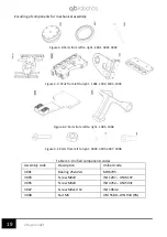
Page 22: ...25x32x4 MR 6705 3003 Screw M2x8 ISO 1207 UNI 6107 3005 Screw M3x8 ISO 4762 UNI 5931 3007 Screw M3x10 SV ISO 10642 3008 Nut M3 UNI 5588 DIN 934 PG Figure 4 2 Parts from left to right 1005 1006 Figure 4 1 Parts from left to right 3003 3005 3007 3008 Figure 4 4 Parts from left to right 2001 3001 3002 Figure 4 3 Parts from left to right 1001 1002 1003 1004 ...

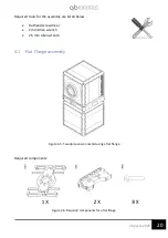
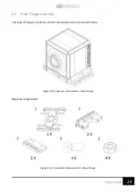
Page 23: ...r the assembly are listed below Flathead screwdriver 2 mm Allen wrench 2 5 mm Allen wrench 4 1 Flat Flange assembly Required components Figure 4 6 Required components for a flat flange Figure 4 5 Two qbmoves connected using a flat flange ...

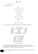
Page 24: ...order to open the locking mechanism Assemble the 1002 parts with the 1001 central core using the two pins as reference Make sure to the orientation of the two components is the same and with the anchor teeth on the same side of the counterbores of the central component Figure 4 7 Flat Flange Figure 4 8 Anchors Opening ...

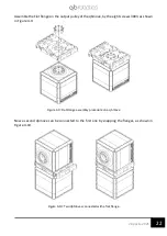
Page 25: ... the qbmove by the eight screws 3003 as shown in Figure 4 9 Now a second qbmove can be connected to the first one by snapping the flanges as shown in Figure 4 10 Figure 4 10 Two qbMoves connected with a flat flange Figure 4 9 Flat Flange assembly procedure on a qbmove ...

Page 26: ...lows the connection of 2 qbmoves can be placed inside the flat flange in two ways First one is shown in Figure 4 11 Another way is shown in Figure 4 12 Figure 4 12 Second possible ERNI cable routing inside a flat flange Figure 4 11 First possible ERNI cable routing inside a flat flange ...

Page 27: ...021 4 2 Base Flange assembly This type of flange is used to connect one qbmove to your desired frame Required components Figure 4 14 Required components for a Base Flange Figure 4 13 qbmove connected to a Base Flange ...

Page 28: ... as shown in Figure 4 15 Assembly of the Base Flange Assemble the two parts obtained with the 1001 central core using the two pins as references Make sure to the orientation of the two components is the same and with the anchor teeth on the same side of the counterbores of the central component Figure 4 16 Base Flange Figure 4 15 Add on assembly procedure ...

Page 29: ...ndence of the first notches as shown in Figure 4 16 Snap the Base flange on one of the free faces of the qbmove Figure 4 18 then using the provided holes screw the entire assembly wherever you need 4 3 C Flange assembly Figure 4 17 qbmoves connected by a C Flange Figure 4 18 Base Flange connected to a qbmove ...

Page 30: ...aring on the free 2001 pulley on the opposite side of the eight treaded holes Assemble the obtained component with the qbmove to reveal the spot remove the plastic bottom cap with a little flathead screwdriver Figure 4 20 Free pulley on qbmove assembly procedure Figure 4 19 Required components for a C Flange ...

Page 31: ...the 1003 component on the free pulley by using eight 3003 screws Assemble the component obtained before and the second 1003 component with the Core using the two pins as reference Figure 4 21 First flange wing assembly procedure ...

Page 32: ...correspondence of the first notches as shown in Figure 4 22 Assembly of the C Flange with the QB move Place the qbmove in the desired position and then close the C Flange Figure 4 23 qbmove C Flange assembly procedure Figure 4 22 C Flange assembly procedure ...

Page 33: ...ws NOTE with the two flanges screwed to the qbmove it is still possible to open the flange to detach or change the orientation of the qbmove 4 3 2 ERNI cable routing in the C Flange The ERNI cable can be routed inside the C Flange as shown in Figure 4 24 Figure 4 24 ERNI cable routing inside the C Flange ...

Page 34: ...ouble Flat Flange assembly This type of flange is used to rigidly connect two qbmoves Required components Figure 4 26 Required components to assemble a double flat flange Figure 4 25 qbmoves connected by a Double Flat Flange ...

Page 35: ...ts as shown in Figure 4 27 The obtained components will be the removable elements of the Double Flat Flange Assemble the two obtained components with the Core using the two pins as reference Place the removable component in correspondence of the first notches of the flanges as shown in Figure 4 28 Figure 4 28 Double flat flange Figure 4 27 Removable component ...

Page 36: ...Assembly the Double flat flange with the qbmove With the double flat flange you can rigidly connect two qbmove with different orientation An example is shown in Figure 4 29 Figure 4 29 qbmove double flat flange assembly ...

Page 37: ...34 28 aprile 2021 4 5 Gripper assembly Required items Figure 4 31 Required components for a qbMove gripper Figure 4 30 qbmove gripper ...

Page 38: ...hown in figure below Assemble the fixed finger on the qbmove closing the Flat Flange and locking it by two 3007 screws as shown in Figure 4 32 Make sure to orient the qbmove as shown in order to have the electrical connectors as indicated Figure 4 33 Fixed finger qbmove assembly procedure Figure 4 32 Fixed finger assembly procedure ...

Page 39: ...aprile 2021 Assemble the second finger component 1006 using the 3003 screws as shown in Figure 4 33 The qbmove must be equipped with a rear pulley as like in a C Flange mounting Figure 4 34 Assembled gripper ...

Page 40: ...37 28 aprile 2021 ...

Page 41: ...38 28 aprile 2021 5 qbmove accessories This chapter shows different kind of variable stiffness robots and accessories available by qbrobotics Moreover some advices to better use your qbmove Advanced kit ...

Page 42: ...d evaluation and assembly examples The payload of the assembled robot will depend on the actuator s torque on the masses on the distances and accelerations Before starting the assembly you must decide which type of robot you want to build and make proper mechanical considerations about the workspace the dynamics and the payload A wrong assembly can drastically reduce the robot s payload when near ...

Page 43: ...actuator When you assemble any robot you must be careful about the distances between flanges and actuator s carter Figure 5 2 because during the use cables or some object can make interference with relative movement of the components To avoid malfunctions after assembly you must manually check the movement of each joint to verify if they work properly IMPORTANT Before using the robot you must chec...

Page 44: ...re below shows the Structure 1 with the Base Flange Figure 5 3 Structure 1 5 2 1 Robot assembly To assembly the robot on the structure follows following three steps 1 open the base flange see 4 1 1 and 4 2 1 Figure 5 4 2 place the first qbmove Advanced of your robot and close the Base Flange Figure 5 5 3 lock the four screws to fix the robot to the structure Figure 5 6 Figure 5 4 STEP 1 Base Flang...

Page 45: ...STEP 2 Placing of qbmove Advanced and closure of flange Figure 5 6 STEP 3 Screws to lock the qbmove Advanced on the structure The structure must be clamped on a solid surface to avoid damages and increase the stability of the robot ...

Page 46: ...ss Robot 5 2 2 1 Configuration Arm 1 Figure 5 7 Variable Stiffness robot Arm 1 and its DoF on the structure 1 This configuration has a first vertical joint to better explore the workspace two horizontal joints to move the Tool Centre Point on a vertical plane and finally a variable stiffness gripper We suggest to set the qbmove ID from the bottom ID 1 to the gripper ID 4 ...

Page 47: ... Stiffness robot Arm 2 and its DoF on the structure 1 This configuration has a first vertical joint the second one is horizontally placed end the third is rotated 90 compared to the previous one We suggest to set the qbmove ID from the bottom ID 1 to the gripper ID 4 ...

Page 48: ...re 5 9 Variable Stiffness robot WRIST and its DoF on the structure 1 This configuration is similar to a robotics wrist with the three consecutive joints perpendicularly assembled We suggest to set the qbmove ID from the bottom ID 1 to the gripper ID 4 ...

Page 49: ...t structure 2 This is an aluminum structure with a Plexiglass as framework and a vertical profile to place your robot arm Following picture shows the components of Structure 2 accessory Figure 5 10 Accessory Structure 2 components ...

Page 50: ... and a component 3019 Figure 5 11 Assembly of two profile for the structure base Use the same components to assemble a symmetrical system make sure to check the quotes Assembly the two bases with the square profile 3015 using nuts 3014 and screws 3010 then assembly a stirrup 3017 and place the cup 3018 Figure 5 12 Assembly of the square profile 3015 ...

Page 51: ...48 28 aprile 2021 Make sure of the correct position of aluminium profiles in order to have a stiff and balanced structure Figure 5 13 Assembly of aluminum profiles ...

Page 52: ...49 28 aprile 2021 Insert in the external guides of profiles four nuts 3014 and 2 cups 3019 Figure 5 14 Figure 5 14 Assembly of the base nuts ...

Page 53: ...5 15 Assembly of the Pexiglass plate 5 3 2 Robot assembly To connect your robot to the structure use a Flat Flange 4 1 open the flange insert four 3008 nuts and connect the flange at the first qbmove Advanced of your robot Figure 5 16 Connection between qbmove Advanced and the Flat Flange ...

Page 54: ...e 5 17 Connection of the robot to the plastic interface Connect the interface to the front surface of the structure inserting it from the top then lock two screws 3010 and place the cup 3018 Figure 5 18 Connection of the robot to the structure You are free to place the robot at the desired height thanks to the graduated strip on the side of the profile ...

Page 55: ...fness Robot We suggest to set the qbmove ID from the frame ID 1 to the gripper ID 4 5 3 3 1 Configuration Arm V1 Figure 5 19 Variable Stiffness Arm V1 This configuration has a first vertical joint to better explore the workspace two horizontal joints to move the Tool Centre Point on a vertical plane and finally a variable stiffness gripper Figure 5 20 Joints of Arm V1 ...

Page 56: ...Stiffness Arm V2 This kinematic has three consecutive vertical joints and a variable stiffness gripper This robot can perform tasks on horizontal plane with high dexterity Figure 5 22 shows a generical configuration of this robot and its dof Figure 5 22 Joints of Arm V2 ...

Page 57: ...puter or perform any computation in this last With qb control you have a totally plug and play experience it is shipped with all needed software already installed and allows you to program the robot to your liking simply publishing and subscribing to ROS topics You can find more details on software usage at section qb control qb control exploits a Raspberry Pi 4 https www raspberrypi org products ...

Page 58: ... them The qbmove GUI will help you to test and use the single qbmove A Simulink package also can be used to control the qbmoves The qbAPI software protocol lets you build a custom program to use the devices you have Afterwards you will see where to find ROS libraries and how to use them to create your project ...

Page 59: ...y 6 2 qbmove GUI The qbmove GUI is an application useful to quickly test a qbmove and eventually to diagnose troubles about the hardware or software You can download the version for your operating system here 6 2 1 Installation procedure Mac If not already installed it is necessary to install the FTDI serial drivers to make possible the device is seen as a serial port Double click on the App and u...

Page 60: ... used Once this command is executed it is necessary to log out and back in for the changes to take effect 6 2 2 Main Layout Application is structured in one tab only Basic Basic commands ID setting activation of the board measurements and currents reading position and current inputs Figure 6 1 qbmove GUI main window ...

Page 61: ...nfo button prints useful information about qbmove and its control board in the blank window on the right side of the application e g firmware version parameters values and position measurements Please remember that in a multi device configuration e g for the Delta Kit see 4 5 ID configuration each qbrobotics device connected to your system must have a unique ID Indeed if any device shares the same...

Page 62: ...1 Clicking on drop down menu will show a list of available IDs 1 to 127 Clicking on Set button will set ID equal to the New ID selected Activation To use qbmove you first have to activate qbmove s drivers You can do this by clicking on Activate The string next to the button will show boar state of activation Measurements and Currents Clicking on Get Measurements and Get Currents will show encoder ...

Page 63: ...60 28 aprile 2021 IMPORTANT Remember to power the qbmove or the chain before using it ...

Page 64: ...Linux MSVC on Windows and Xcode on macOS If you have any trouble during this installation requirement have a look at the MATLAB documentation to find the proper way to install a C compiler on your system https it mathworks com help matlab ref mex html 6 3 1 3 Compile the library If the previous steps are fine navigate under your_working_directory qbmove_simulink in the MATLAB tree explorer and the...

Page 65: ...he block The block inputs have the following functions Handle Is used to connect the QB Move Init block which stores the serial port Pos 1 This input depends on the Input modality set It could have 2 values pos 1 or eq pos The first one is used when the Prime Movers Modality is chosen the second one is used when one between Equilibrium Position and Stiffness Preset or Equilibrium Position and Stif...

Page 66: ...the explanation follows below ID If it is connected only one device the ID could be put without brackets otherwise the syntax is like in the picture Communication direction Is used to show which ports are shown on the block If it is on Both the block will have the ports like on the above image If it is on Tx it will have only the output ports If it is on Rx it will have only the input ports Input ...

Page 67: ...an Activation input port will show and a 0 1 signal should be routed to that input port Watchdog Timer Setting this value to a value different from 0 will set a parameter on the device that is going to deactivate that device if it doesn t receive inputs in the time defined by the Timer Unit This parameter defines the measurement unit of the inputs and outputs of the device The Tick value is referr...

Page 68: ...Options panel It is possible to set the IDs of the devices connected in the same way of the QB Move block The input port in order to retrieve the currents must be connected to the output of the QB Move Init block The outputs are the currents of motors of the devices qbmove Get Curr and Meas This block works the same way of the QB Move block but with also the benefit of the QB Move Get Current bloc...

Page 69: ...ake the simulation go as the same velocity as the devices connected As you can see in the following example is always used with a Clock to see if the commands of the simulation are going at the same velocity of the device or slower Figure 6 8 qbmove Get Current and Measurements block Figure 6 9 qbPacer block ...

Page 70: ...unning and you can see the device will move In this case the input modality is chose to be Equilibrium Position and Stiffness Preset so the example as it is will work only on a qbmove On the right there are 3 displays where you can read the values in the measurement unit chosen of the 3 sensors depending on the device used the value of the outputs changes Refer to previous section for better expla...

Page 71: ...qbrobotics to help in a quicker kinematic structure control You can inspect the example by opening the Simulink model your_working_directory qbmove_simulink examples delta qbdelta_r2018 slx which is valid from MATLAB r2018a on while qbdelta_r2017 slx refers to previous MATLAB version 6 3 3 1 Inverse kinematics and control inputs A specific Delta Kit controller has not been implemented since each s...

Page 72: ...ze the URDF model and give a remote feedback on what is happening in the real system IMPORTANT It is worth noticing that this is just a state visualizer and not a simulator 6 4 qbAPI software protocol 6 4 1 Compiler Installation Before using the qbAPI on your system if not already installed it is good use to install a C compiler Below here are listed all the necessary instructions for each operati...

Page 73: ...when it is needed All the functions have an explanation in form of comments in qbmove_communications h Following here there will be a brief explanation of the functions and what are used for 6 4 3 Basic Functions In most cases these will be all the necessary functions that you will need to use the qbmove within your system RS485ListPorts Description This function is used to retrieve the name of al...

Page 74: ...s correctly activated or deactivated It is needed an inactive program time if used right after the commActivate Arguments comm_settings comm_settings_t Structure containing info about communication settings int id The device s ID number char activate Device activation status commSetPosStiff Description This function is used to give the device reference inputs to motors Is used only with a qbmove d...

Page 75: ...d to retrieve both motor currents and encoder measurements from the device with only one command Arguments comm_settings comm_settings_t Structure containing info about communication settings int id The device s ID number short int values The array used to store motor currents and encoder measurements of the device connected 6 4 4 Code Examples 6 4 4 1 Theoretical Example The purpose of this examp...

Page 76: ...tilities as described in previous section and then run g qbmove_example cpp libqbmove_comm a o qbmove_example qbmove_example exe Code include iostream include string h ifdef _WIN32 include windows h else include unistd h endif include include qbmove_communications h define TRUE 1 define FALSE 0 int main int argc char argv char serial_ports 10 255 int serial_ports_count RS485listPorts serial_ports ...

Page 77: ...p 1000 else usleep 1000000 endif char status int result commGetActivate file_descriptor device_id status if result 0 std cout ERROR tfails while activating motor std endl return 1 short int currents 2 currents of each of two motors short int positions 3 data from encoder motor 1 motor 2 and shaft respectively if commGetMeasurements file_descriptor device_id positions 0 std cout ERROR tfails while ...

Page 78: ...FO tshaft middle position minimum stiffness std endl ifdef _WIN32 Sleep 1000 else usleep 1000000 endif commands 0 3300 little movement shaft commands 1 32000 max stiffness commSetPosStiff file_descriptor device_id commands std cout INFO tlittle movement shaft max stiffness std endl ifdef _WIN32 Sleep 1000 else usleep 1000000 endif commands 0 15000 max positive turn commands 1 16000 middle stiffnes...

Page 79: ...iddle stiffness std endl ifdef _WIN32 Sleep 1000 else usleep 1000000 endif commActivate file_descriptor device_id FALSE deactivate motor ifdef _WIN32 Sleep 1000 else usleep 1000000 endif result commGetActivate file_descriptor device_id status if result 0 std cout ERROR fails while deactivating motor std endl return 1 std cout Demo finished std endl closeRS485 file_descriptor return 0 6 5 ROS ...

Page 80: ... 6 5 2 1 for an overview of the C classes 6 5 1 3 Sources Another common apporach to install ROS packages is to clone their sources in the Catkin Workspace and then recompile everything which is pretty straightforward for a ROS user The following steps show how to do it even for ROS beginners 1 Clone both the qb_device qb_move and qb_chain packages to your Catkin Workspace e g catkin_ws cd catkin_...

Page 81: ...t hw ros kinetic trac ik kinematics plugin and their dependencies e g use sudo apt install ros pkg 6 5 1 4 Device setup Connecting a qbmove to your system is basically a matter of plugging in a USB cable Nonetheless read carefully this manual to understand all the requirements and advices about either single device or chained configurations e g the Delta kinematic structure of this manual 6 5 2 Us...

Page 82: ...on Handler and it is usually started in a separate terminal Please remember that in a multi device configuration e g for the Delta Kit see 4 5 ID configuration each qbrobotics device connected to your system must have a unique ID Indeed if any device shares the same ID with another one on the same chain all the qbmove devices have ID equals 1 when they are shipped from qbrobotics communication iss...

Page 83: ...licitly during the initialization of a control Node If the Communication Handler finds fewer or even more devices than expected check the device IDs to be sure that there are no devices that are sharing the same ID This check can be easily achieved by connecting one device at a time and starting the Communication Handler each time This is a simple example when starting the Communication Handler wi...

Page 84: ...e user to send commands to the relative device and get its measurements From an API point of view it is implemented an Action Client which matches the relative trajectory controller and provides a method to send Goals i e command references directly to the given device Additionally the Action Client is subscribed to a Topic _controller command that can be used to send reference commands from outsi...

Page 85: ...l control launch standalone true activa te_on_initialization true device_id actual_device_id The arguments explained activate_on_initialization false Activates the motors at startup the device will not move since the first command reference is received device_id 1 Each device has its own ID you need to set the one of the actual device connect to your system standalone false Starts the Communicatio...

Page 86: ...to mark retrieved data as corrupted set_commands true Choose whether or not to send command positions to the device set_commands_async false Choose whether or not to send commands without waiting for ack use_rviz true Choose whether or not to use rviz If enabled you should see a virtual qbmove on screen performing a similar behavior i e moving the shaft and both the actuators accordingly When the ...

Page 87: ...the bottom 1 Select the Controller Manager namespace from the left menu e g robot_namespace control controller_manager where robot_namespace is an additional argument of the launch file needed with several devices This enables the right menu which provides all the controllers available for the connected device 2 Select the qbmove controller from the second dropdown menu and enable it through the c...

Page 88: ...n modify the waypoint trajectory to replicate the behavior you want either change the robot_package _control config robot_name _waypoints yaml or add another custom application specific file in the config directory In the second case you need to set the argument robot_name properly when launching the command from the terminal The waypoint configuration is as follows Waypoints describe the desired ...

Page 89: ...ur application Don t reinvent the wheel At last if you come up with a something useful for the whole community it will be amazing if you propose your improvement with a Pull Request in the package of interest on our Bitbucket 6 5 3 Delta robot and open kinematic chains examples When using the ROS packages with a Delta Kit or a Base Kit with specific accessories it is possible to exploit the specif...

Page 90: ...he structure of these files will de described in the next section IMPORTANT It is worth noticing that this is just a state visualizer and not a simulator 6 5 3 2 Dedicated controller A specific Kit controller could have not been implemented since each single qbmove controller can be exploited to control the whole system Anyway controlling a kinematic structure only w r t the joint space is not the...

Page 91: ...tools are exploited in ArmV2KinematicController Arm2KinematicController and WristKinematicController 6 5 3 3 Interact with robots Currently it is possible to interact with robot in three different ways 1 Publishing messages in a specific topic In this case you have to specify The end effector desired position to reach each qbmove stiffness the velocity with which the robot has to move This is a sc...

Page 92: ...u can set the end effector roll angle The message is as follows rostopic pub qbarm_v2 control arm_v2_controller t arget_poses_and_roll qb_chain_msgs MoveAndRotateCh ain move_robot target_pose header seq 0 stamp secs 0 nsecs 0 frame_id point x 0 02 y 0 16 z 0 0 motor_stiffnesses 1 1 1 velocity 0 4 type_of_movement moveJ roll 0 2 Using waypoints In this case you can choose the list of points in Cart...

Page 93: ...he last available value waypoints time 1 0 joint_stiffness 0 75 0 75 0 75 end_effector 0 0 0 0 0 15 gripper 0 0 0 5 time 3 0 4 0 stiffness is not changed in this case end_effector 0 0 0 07 0 15 gripper 0 0 0 5 time 5 0 joint_stiffness 0 5 0 5 0 5 end_effector 0 0 0 07 0 15 gripper 1 0 0 5 To use this control mode you have to set the optional argument use_waypoint to true for example roslaunch qb_c...

Page 94: ...become more confident with these kinematic structures and their operative space Moreover a simple test when inventing a demo application can be done more quickly in this way To use this control mode you have to run the command roslaunch qb_chain_control robot_config _control launch standal one true activate_on_initialization true use_rviz true 6 5 4 qb control If you purchased the qb control modul...

Page 95: ...rocedure is complete before you proceed with the next steps you have to edit the qb_control_chain sh sh file in order to specify your IP So edit the line ROS_IP 192 168 X XX and insert the IP of your computer You can find it typing from terminal the command ipconfig Now follow these steps 1 Connect to the WI FI network qbRPi4 hub password qbrobotics 2 from terminal move to the folder in which you ...

Page 96: ...from terminal the command ifconfig and in the same shell use the way you prefer to interact with the kinematic structure 6 5 5 ROS packages overview You can find all the needed packages here qb_device http wiki ros org qb_device qb_move http wiki ros org qb_move qb_chain http wiki ros org qb_chain ...

Page 97: ...94 28 aprile 2021 This page was intentionally left blank ...

Page 98: ...95 28 aprile 2021 7 Troubleshooting This chapter explains how to solve problems that you may encounter in the process of building a robot programming a robot file or operating a robot platform ...

Page 99: ... the shaft Solution 02 Connect qbmove to the PC and run qbmove GUI Make sure that the sliders of position and stiffness are in zero position then activate the qbmove Once activated you can move the device by moving the sliders To reset the position to zero click on Zero button In this way shaft will go to zero position and minimum stiffness configuration You can then use the sliders to verify the ...

Page 100: ...nd the device doesn t move change the daisy chain port 7 4 White LED is off when you use the robot Cause The white LED is damaged or the actuator doesn t receive the electrical supply from a previous actuator of the power chain or from the USB cable Troubleshooting _____________________________________________________________________________ Solution 01 Connect qbmove to your pc using the USB cabl...

Page 101: ...ound Device Manager Open the Ports COM LPT drop down menu right click on the COM port and select Proprieties Select the Port Settings tab and then click on Advanced Once in Advanced menu select from the drop down menu a COM number between COM1 and COM9 and click on OK Solution 02 Check if the one or more led is on if it is Try changing USB post on your computer If it is not change the USB cable or...

Page 102: ... 28 aprile 2021 8 Commissioning and Maintenance This chapter explains how to solve problems that you may encounter in the process of building a robot programming a robot file or operating a robot platform ...

Page 103: ...ters The drive performing unplanned movements during commissioning cannot be ruled out Make sure that even if the drive starts to move unintentionally no danger can result for personnel or machinery 8 2 Maintenance and warranty Products of the company qbrobotics s r l are produced using the most modern production methods and are subject of strict quality inspections All sales and deliveries are pe...

Page 104: ...fness observer vsa devices html A Stiffness Estimator for Agonistic Antagonistic Variable Stiffness Actuator Devices http www centropiaggio unipi it publications stiffness estimator agonistic E2 80 93antagonistic variable stiffness actuator devices html Variable Stiffness Control for Oscillation Damping http www centropiaggio unipi it publications variable stiffness control oscillation damping htm...

Page 105: ...ly vsa peg hole html Passive impedance control of a Qboid multi DOF VSA CubeBot manipulator http www centropiaggio unipi it publications passive impedance control qboid multi dof vsa cubebot manipulator html Open Source VSA CubeBots for Rapid Soft Robot Prototyping http www centropiaggio unipi it publications open source vsa cubebots rapid soft robot prototyping html Robust Optimization of System ...

Page 106: ...18 First version 2 10 08 08 18 Updated ROS section 2 11 23 10 18 Updated ROS section 2 12 16 04 19 Updated Electrical connections section 2 20 22 09 2020 Update paragraph 6 3 and 6 5 2 30 19 03 2021 New chapter 5 qbmove accessories and update of ch 6 2 40 28 04 2021 Fixing of chapter 6 ...

Reviews: