ATTENTION:
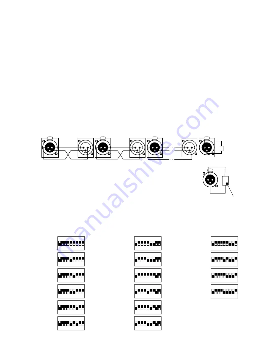
DMX addresses setting example
for 16 16-channel scanners.
1
7
(97)
13
(193)
2
(17)
8
(113)
14
(209)
3
(33)
9
(129)
15
(225)
4
(49)
10
(145)
16
(241)
5
(65)
11
(161)
6
(81)
12
(177)
3. CONTROLLER AND EFFECTS CONNECTING
The Mirage controller sends out the signals compatible with the DMX-512 standard. The proper
operation of the whole set requires the correct setting of the DMX addresses in the controlled
devices and the correct connection between the devices, made with the signal cable.
Below are a few practical tips:
1. To connect the devices use a microphone cable (two strands in a shield).
2. Connect all the XLR couplings according to the following pattern:
pin 1 = shield
pin 2 = DMX-
pin 3 = DMX+
3. The controller and all the effects must be connected in series only, that is:
- the controller output to the first effect input,
- the first effect output to the second effect input,
- the second effect output to the third effect input, etc.
4. The "terminator" must be installed in the last device's DMX output socket
nd
rd
(XLR plug with the 110 Ohm resistor between 2 and 3 pin installed).
5. Set the DMX addresses in the controlled effects according to the following pattern:
2
PRACTICAL COMMENT:
The older devices produced by MARTIN company have switched "DMX+" and "DMX-" lines. That
is why the special signal cables with interweaved signal lines should be prepared to connect
these devices.
2 3 4 5 6 7 8 9
ON
DIP
1
2 3 4 5 6 7 8 9
ON
DIP
1
2 3 4 5 6 7 8 9
ON
DIP
1
2 3 4 5 6 7 8 9
ON
DIP
1
2 3 4 5 6 7 8 9
ON
DIP
1
2 3 4 5 6 7 8 9
ON
DIP
1
2 3 4 5 6 7 8 9
ON
DIP
1
2 3 4 5 6 7 8 9
ON
DIP
1
2 3 4 5 6 7 8 9
ON
DIP
1
2 3 4 5 6 7 8 9
ON
DIP
1
2 3 4 5 6 7 8 9
ON
DIP
1
2 3 4 5 6 7 8 9
ON
DIP
1
2 3 4 5 6 7 8 9
ON
DIP
1
2 3 4 5 6 7 8 9
ON
DIP
1
2 3 4 5 6 7 8 9
ON
DIP
1
2 3 4 5 6 7 8 9
ON
DIP
1
11
0
O
h
m
martin
scanner no. 2
last scanner
CONTROLLER
SHIELD
SHIELD
DMX -
DMX +
DMX -
DMX +
1
2
3
PUSH
1
2
3
PUSH
1
2
3
PUSH
1
2
3
PUSH
2
1
3
2
1
3
2
1
3
110 Ohm
resistor
11
0
Oh
m
1
3
PUSH
2


