


October 2003
Page 16–9
Chapter 16. Universal Checkback Module
16
Step 1. Unpack the module.
||Open the carton and remove the Universal
Checkback Module. Check the software versions
of all checkback modules working together to
make sure they are the same basic revision, espe-
cially if they were shipped from Pulsar at different
times. Revision 1.0x will not work with revision
2.0x, for example. For optimum operation all
modules should be the same revision. Check
Pulsar's website for PLC software downloads to
upgrade to the latest revision. You can check the
version by looking at the label on the programmed
chip (U4) on the Universal Checkback module. If
this is missing then you will need to connect a
computer to the 9-pin serial connector on the front
of the module and power it up. Refer to Fig. 16-4.
Before operating the Universal Checkback
modules, verify that manual keying (using the HL
& LL pushbuttons on front of the Keying module)
of both transmitters gives a correct response at the
corresponding far end receiver. LL (low level)
keying should give -10 dB on both the local and
far end Receiver module. HL (high level) keying
should give 0 dB on both the local and far end
receiver module. NOTE: The self-adjusting
receiver has two sensitivity settings that need to be
made. The first one is for setting with the far end
transmitter keyed to 10W (HL) and the second
sensitivity (local) setting is for the local trans-
mitter keyed to 10W (HL).
For a 3-terminal line you have to set each receiver
module to the weakest transmitter signal coming
in. Only for the weakest remote transmitter and for
your local transmitter will you see 0 dB for HL
keying and -10 dB for LL keying. Other transmit-
ters will have a higher signal level (shown on the
Receiver module).
For installations where you have not already tried
known settings it is recommended you first try
Pulsar's standard factory settings regardless of
your final desired settings. This allows you to
know that at least the system works with standard
factory settings, and then you can check for incon-
sistencies in your settings if your settings don't
work and the standard factory settings do.
For 2-terminal lines set the Universal Checkback
module that you want to be the master to Factory
Setting # 1 by setting the 4 position DIP switch
(S1) to have position 1 down (ON) and all other
three positions up (OFF). Note that the green LED
#1 will come on when it is set to factory setting #1.
Then set the other Universal Checkback module
that you want to be the remote to Factory Setting
# 2 by setting the 4 position DIP switch (S1) to
have position 2 down (ON) and all other three
positions up (OFF). Note that the green LED #2
will come on when it is set to factory setting
#2.These particular factory settings should give
you a green "CHECK OK" LED after performing
a checkback test. Then you can you change the
settings to whatever you desire and try again.
For 3-terminal lines you can do something similar
as for 2-terminal lines above. Set the master to
Factory Setting # 1 and the first & second remotes
to Factory Setting # 2. Then using a computer
change the master, first remote, and second remote
settings to say "Last Remote = 2" by typing "set
last 2", and in addition change the second remote
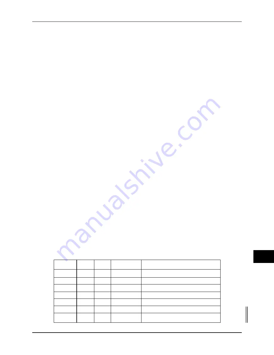
Table 16–2. Universal Checkback Module DIP Switch Settings.
S1
S2
S3
S4
Settings Option
off
off
off
not used
Custom Settings Enabled
on
off
off
not used
Factory Preset #1 Settings
off
on
off
not used
Factory Preset #2 Settings
on
on
off
not used
Factory Preset #3 Settings
off
off
on
not used
Factory Preset #4 Settings
on
off
on
not used
Factory Preset #5 Settings
off
on
on
not used
Factory Preset #6 Settings
Summary of Contents for TC-10B
Page 2: ...Technologies Inc...
Page 12: ...Technologies Inc...
Page 22: ...Page 1 10 October 2003 TC 10B System Manual Technologies Inc Technologies Inc USER NOTES...
Page 44: ...Page 2 22 October 2003 TC 10B System Manual Technologies Inc Technologies Inc USER NOTES...
Page 53: ...3 Figure 3 3 TC 10B Mechanical Outline Drawing 1354D48...
Page 56: ...Page 3 12 October 2003 TC 10B System Manual Technologies Inc Technologies Inc USER NOTES...
Page 58: ...Page 4 2 October 2003 TC 10B System Manual Technologies Inc Figure 4 1 Extender Board...
Page 90: ...Figure 9 2 TC 10B TCF 10B Power Supply Component Location 1617C38...
Page 91: ...9 Figure 9 3 TC 10B TCF 10B Power Supply Schematic 1617C39...
Page 92: ...Page 9 6 October 2003 TC 10B System Manual Technologies Inc Technologies Inc USER NOTES...
Page 97: ...10 Figure 10 2 TC 10B Keying PC Board 1495B69...
Page 98: ...Figure 10 3 TC 10B Keying Schematic 1606C29...
Page 104: ...Figure 11 3 TC 10B TCF 10B Transmitter PC Board 1500B10...
Page 106: ...Figure 11 5 TC 10B Transmitter Block Diagram 1610C09...
Page 107: ...11 Figure 11 6 TC 10B Optional TTL Transmitter Component layout CC20 TXMA1 001...
Page 112: ...Figure 12 2 TC 10B TCF 10B 10W PA PC Board 1495B73...
Page 113: ...12 Figure 12 3 10W PA Schematic 1606C33...
Page 114: ...Page 12 6 October 2003 TC 10B System Manual Technologies Inc Technologies Inc USER NOTES...
Page 117: ...13 Figure 13 2 TC 10B TCF 10B RF Interface PC Board 1609C32...
Page 118: ...Figure 13 3 TC 10B TCF 10B RF Interface Schematic 1609C32 2...
Page 126: ...Page 14 8 October 2003 TC 10B System Manual Technologies Inc Technologies Inc USER NOTES...
Page 132: ...Figure 15 3 TC 10B Receiver Output PC Board CC50RXSM...
Page 133: ...15 Figure 15 4 TC 10B Receiver Output Schematic CC30RXSM...
Page 134: ...Page 15 8 October 2003 TC 10B System Manual Technologies Inc Technologies Inc USER NOTES...
Page 178: ...Page 16 44 October 2003 TC 10B System Manual Technologies Inc Technologies Inc USER NOTES...
Page 184: ...Figure 17 3 Voice Adapter Module PC Board C020VADMN...
Page 189: ......
Page 190: ...Technologies Inc...


