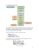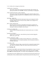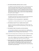
At the end of the X/Y calibration, the printer measures the reference height above
each of the 9 bed sensor points and stores the reference heights in nonvolatile
memory. During normal bed leveling, it is expected that the PINDA probe triggers no
more than 1 mm from the reference value, therefore the nozzle is not allowed to
move more than 1 mm below the reference value during the bed calibration.
If you moved the printer, you may need to re-run the Z calibration to sample new
reference Z height values reflecting the twist and bend of the table surface the printer
is sitting on. If that does not help, please verify, that the PINDA probe is aligned with
the sensor points on the print bed during the bed Z calibration. The alignment shall
be ensured by the automatic X/Y calibration routine. If the PINDA probe is not
aligned during the Z calibration over time, it is possible, that a pulley is slipping or
something on the machine’s frame got loose.
3)
Bed leveling failed. Sensor triggered too high. Waiting for reset.
Similar to case 2). This time the PINDA sensor triggered more than 1 mm above the
reference height. Before doing anything else, make the Z axis level by going all the
way up and try again.
6.2.5.2 Y axis alignment
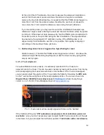
For autocalibration to work properly, it is extremely important for the Y axis to be
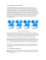
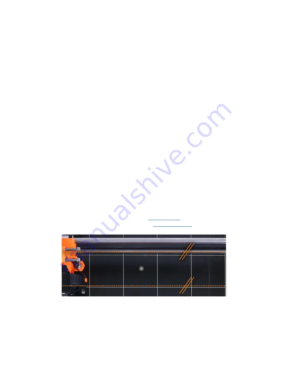
perpendicular to the X axis. This can be easily checked by looking at the printer from the top
and visually aligning the X-axis rods with lines on the heatbed. If the Y axis is misaligned,
you can easily adjust the position of the Y axis inside the frame by loosening the
M10 nuts
on the Y axis and securing them at the newly adjusted position. You can see how in the
Original Prusa i3 MK2S kit assembly manual
7.PSU/Step 20
(check if everything is
correct ) or in P.I.N.D.A. Probe Misaligned topic at
help.prusa3d.com
.
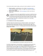
Pic. 7 - X-axis rods must be visually aligned with lines on the heatbed.
If the Calibrate XYZ gives “
XYZ calibration compromised. Front calibration points not
reachable.
” error, you don’t necessarily need to adjust the M10 nuts and position of the axis
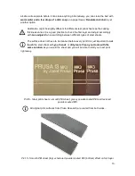
in the frame, but you can adjust the belt holder position.
Y-belt-holder with a slot allows to
19
Summary of Contents for i3 MK2.5
Page 1: ......
Page 64: ...Pict 40 Nozzle change 64 ...

