Version 1.0
Version 1.0
Installation
25
25
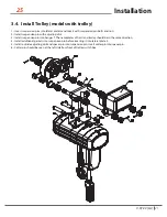
3.4. Install Trolley (models with trolley)
1.- Insert suspension pins into lateral plate G and lock it with suspension pin bolts and nuts.
2.- Install suspension pin with adjusting disk.
3.- Install suspension pin into hanger T. The nameplates of hoist and trolley should be in the same direction.
4.- Install additional gaskets into suspension pin before inserting it into lateral plate S.
5.- Install outside adjusting disk and spacer pin into suspension pin. Insert cotter pin into spacer pin.
6.- Cotter pin should be seen at the left side from front of trolley switch box.
V.07.22 [LA]
Summary of Contents for PWJTHF
Page 2: ...This page intentionally left blank...
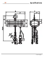
Page 19: ...Version 1 0 19 Specifications 19 V 07 22 LA...
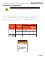
Page 20: ...Version 1 0 Specifications 20 20 V 07 22 LA...
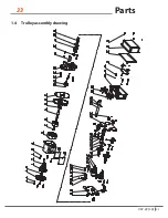
Page 33: ...Version 1 0 33 Parts 33 1 4 Trolley assembly drawing V 07 22 LA...
Page 49: ...49 Wiring Diagram 49 7 CONVENTIONAL HOIST WIRING DIAGRAM PWJTHF PWJTHT V 07 22 LA...

