background image

CONFIGURATION

PRO-VISION

®


Video Systems


DVR-906M SYSTEM GUIDE 


53 

provisionusa.com


Basic DVR Settings 

Basic DVR settings are adjusting by clicking on the settings button in the upper right 
corner of the web page and then selecting the category from the drop-down menu. 


Power Settings: 

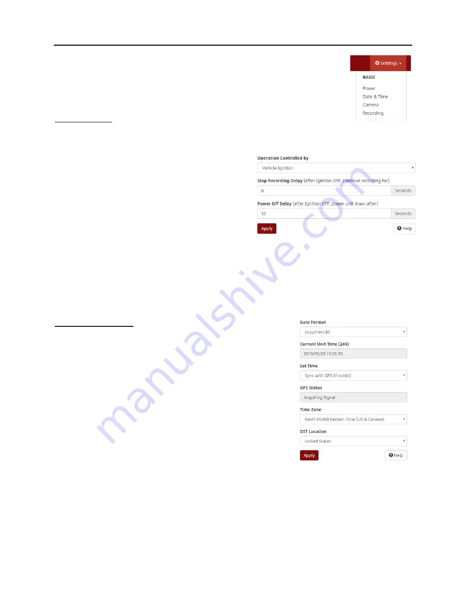
The power settings allow the user to set when the system turns on and off.  By default, the system will 
turn on with the vehicles ignition and turn off 1800 seconds (30mins) after the key is turned off. 

Operation Controlled by:


Set to “Vehicle Ignition” for normal operation, this can be 
changed to “Schedule” to set certain times of the day to 
power the system on/off rather than by ignition state.


Stop Recording Delay:


Set the number of seconds after the key turns off that the 
DVR unit will continue to record for. Commonly this is set 
to 600 seconds (10 min) regardless of the power down 
time.


Power Off Delay:


This setting is used to configure the amount of time the DVR will continue to remain powered on and 
active after the vehicle ignition has been turned OFF, this works in conjunction with the “Stop Recording 
Delay” setting above. If the vehicle is not using Wi-Fi transfer this is commonly set to 600 seconds. If Wi-
Fi transfer is used this setting is normally set around 3600 seconds (1 hour) to allow sufficient time to 
transfer data.


Date & Time Settings: 

Date Format:


Allows the user to select which date format as it will appear on the 
video. 

Current Unit Time (24h):


Shows the time the DVR is currently set at.  

Set Time:


Allows the user to choose how time is set: 

o

  Sync with GPS (if exists) 

o

  Keep Current Settings - Will not change any time or date 

information. 

o

  Manually Set - Provides areas where the date and time can be 

set by the user. Click in each box to enter the text. Once 
finished, click the “Update” tab at the bottom of the page. 

o

  Sync with Device Time - Shows the current date and time of the device you are using to program 

your DVR. 

GPS Status:


Displays the current GPS status to show if GPS can synchronize the time. 

Time Zone:


Summary of Contents for DVR-906M

Page 1: ...6 11 2020...

Page 2: ...shboard and SecuraMax are registered trademarks of PRO VISION Solutions LLC All other products or name brands mentioned herein are the property of their respective owners SOFTWARE AND FIRMWARE UPDATES...

Page 3: ...e SSD Installation 50 CONFIGURATION 51 DVR Status Lights 51 Connecting to the DVR 52 Setup Wizard 52 Basic DVR Settings 53 Advanced DVR Settings 57 OPERATION 62 DVR Status Lights 62 Viewing Cameras on...

Page 4: ...TION PRO VISION Video Systems DVR 906M SYSTEM GUIDE 2 provisionusa com INSTALLATION Installation Quick Guide This page is designed for quick reference Continue further in this guide for detailed instr...

Page 5: ...PD 1771 Power Cable with Two 2 Inline Fuse Holders 1 PD 1772 Camera 1 Camera 2 Interface Cable 1 PD 1773 Camera 3 Camera 4 Interface Cable 1 PD 1774 Standard Definition A V Output Cable 1 PD 1833 GPS...

Page 6: ...821 Digital HD Wide Angle Mini Dome Camera with 20ft Cable and Mounting Hardware DVR 824 Digital HD Dual Lens Stop Arm Camera with 20ft Cable and Mounting Hardware Analog HD Camera Kit Options Photo...

Page 7: ...7 LCD Monitor Kit with Harness 15ft A V Cable DVR Cable Mounting Bracket and Hardware PM 1910S 9 Quad View LCD Monitor Kit with Harness 15ft A V Cable DVR Cable Mounting Bracket and Hardware Storage R...

Page 8: ...ailer Receiver Kit with 33ft Analog A V Cable and Mounting Hardware PD 1771 Power Cable with Two 2 Inline Fuse Holders PD 1975 Hybrid HD Video Output Cable PD 1977 Hybrid HD Cable Pack with Cam1 2 Cab...

Page 9: ...desired operation Front of DVR Rear of DVR 1 SDXC Card Slot 1 Power Cable Connection 2 Record STOP Button 2 GPS EVT Triggers Cable 3 4G Status Indicator 3 HD A V Output Connection 4 4G SIM Card Slot 4...

Page 10: ...nts 32GB SDHC P N PD 1716 64GB SDXC P N PD 1718 128GB SDXC P N PD 1728 256GB SDXC P N PD 1738 IMPORTANT The SD card can only be inserted into the unit with the contacts first and label facing away fro...

Page 11: ...ge that is not affected by the typical vibration experienced in a mobile environment Solid State Drives are available in multiple capacities 500GB SSD P N DVR 830 1TB SSD P N DVR 831 2TB SSD P N DVR 8...

Page 12: ...eo Output Cable This cable is used to output the live video and audio from the DVR unit to a display monitor for aiming the cameras or real time observation of the camera view s It includes a temporar...

Page 13: ...ends connect to the DVR Note Two 20ft cables cannot be connected to each other If more than one cable is needed the PX 1843 30ft Digital HD Extension Cable must be used PX 1843 30ft Digital HD Extens...

Page 14: ...on Access to the front of the DVR to view lights and or remove storage media Access to insert and turn key to remove cover test for accessibility if necessary Access to the rear of the DVR for service...

Page 15: ...ource then the setting for Ignition Level must be changed in the power menu to the proper LOW level setting before final connection to the ground level source BLACK Chassis or Battery Ground The groun...

Page 16: ...and PD 1773 interface cables shown below Analog HD Camera Cables Connections Cameras can be either directly connected or connected through analog A V cables PX 1942 5m 16ft Analog A V Cable PX 1943 10...

Page 17: ...n 1 Disassemble the camera by loosening the three 3 hex head set screws located on the locking ring Lift up on the locking cover and remove it from the camera assembly Remove the camera ball and pull...

Page 18: ...llowing the camera ball to freely move until the desired camera aim is set 11 Power on the DVR unit and connect to the Wi Fi to view the live camera image to properly aim it on the view page See Viewi...

Page 19: ...nation with a monitor the camera should be mounted as far toward the front of the vehicle as possible When mounting to the vehicle consider spray and debris from the tires could affect the camera imag...

Page 20: ...camera is aimed 9 Power on the DVR unit and connect to the Wi Fi to view the live camera image to properly aim it on the view page See Viewing Cameras on a Smart Device for connection details 10 After...

Page 21: ...era by loosening the two 2 threaded lock rings removing them and sliding them off the cable and connector Then removing all the spacer rings 3 Determine the order of the spacers as needed based on the...

Page 22: ...replace the center most marker light to provide the driver with the most natural view Installation 1 Locate the desired mounting location remove the existing light to check for proper clearance for t...

Page 23: ...is found mark or measure the two 2 mounting screw hole locations in the camera If license plate mounting skip this step 3 If the cable will be routed through the vehicle body it is common to drill a h...

Page 24: ...camera It is recommended to power on the DVR unit and temporarily connect the camera to it and observe that the view in the desired mounting location is satisfactory before proceeding to the next step...

Page 25: ...al of the camera if necessary for service in the future Typically 4 6 15 Power on the DVR unit and connect to the Wi Fi to view the live camera image to properly aim it on the view page See Viewing Ca...

Page 26: ...the connector until a click is heard The HD cameras and cables use a sliding quick release collar on the female connectors holding this connector by the sliding metal collar will make it difficult for...

Page 27: ...east 4 of slack near the camera connection points to allow future servicing of cameras 5 If excess cable is present this can be doubled over or wound up After all cables are run you may wish to use ca...

Page 28: ...amera 6 Digital HD Camera 5 Digital HD Camera 7 Digital HD Camera 6 Digital HD Camera 5 Digital HD Camera 7 Digital HD Camera 6 Digital HD Camera 8 Digital HD Camera 5 Digital HD Stop Arm Camera 7 and...

Page 29: ...room to route the cable behind the camera s mounting location Installation 1 Disassemble the camera by loosening the three 3 Phillips head screws on the camera housing base Then separate the bottom b...

Page 30: ...camera over the ball in the same order as removed ensure that the three 3 mounting screws align with the holes in the base 10 Using a Phillips screwdriver tighten each of the three 3 screws leave the...

Page 31: ...rews through the holes on each side of the bracket into the camera Install these screws only finger tight as final adjustments to camera aim will need to be made later 2 Remove the film from one side...

Page 32: ...or downward after mounting Installation 1 Gently spread the two sides of the bracket apart and slide the camera in place with the pivot pins on each side of the bracket aligned to the center hole on...

Page 33: ...llow removal of the camera Typically 4 6 9 Install the four 4 side mounting screws into the side of the camera through the bracket using a lock washer and washer on each Do not tighten the screws unti...

Page 34: ...ntly spread the two sides of the bracket apart and slide the camera in place with the pivot pins on each side of the bracket aligned to the center hole on each side of the camera as show in the image...

Page 35: ...ack to allow removal of the camera Typically 4 6 25 Install the four 4 side mounting screws into the side of the camera through the bracket using a lock washer and washer on each Do not tighten the sc...

Page 36: ...ectly above the wire panel running above the side windows of the passenger area Do not mount camera with any light source directly in the field of view as it will affect the picture quality Standard B...

Page 37: ...nnect to the Wi Fi to view the live camera image to properly aim it on the view page See Viewing Cameras on a Smart Device for connection details 10 After the camera is aimed tighten the four 4 mounti...

Page 38: ...for the camera to recess into the holes are 1 25 diameter and 2 apart as shown in RED color to the right 7 Use a shears or grinding tool to cut the remaining material between the two holes out as show...

Page 39: ...directly next to the vehicle Always check the mounting structure under the camera to ensure that proper access to route the cable is possible Installation 11 Remove the three 3 Allen head cover mounti...

Page 40: ...nd the mounting surface to ensure the hardware has clearance DO NOT completely tighten hardware yet 17 Place the dome ball into its socket in the camera base and ensure there is enough camera cable to...

Page 41: ...aside the three 3 hex head screws located on the locking ring Lift up on the locking ring and camera housing to remove them from the camera assembly Remove the camera ball and pull the cable through...

Page 42: ...ring over the camera ball Ensure that the three 3 mounting screw holes on the locking ring align with the holes in the mounting base 20 Using a 2mm Allen wrench begin to tighten each of the three 3 sc...

Page 43: ...truct vehicle license plate capture Recommended mounting shown at right 6 18 below the bottom of the stop sign on the stop arm itself 12 60 from the center of the open stop arm forward or rearward On...

Page 44: ...LL THE OTHER HOLES 4 Using the female end of the camera connection or extension cable verify there is enough clearance for the connector to fit through the hole and route toward the recording unit If...

Page 45: ...le to the Camera 7 port on the DVR unit for the camera to be recognized IMPORTANT The Nyloc nuts used for mounting the camera experience reduced holding performance after each removal and reinstallati...

Page 46: ...surface and hold for 30 seconds It is recommended to allow adhesive to cure for 1 hour prior to attaching monitor 3 Locate your ignition controlled power and ground locations in the vehicle A fused l...

Page 47: ...ehicle A fused location is not needed as the power harness for the monitor includes an inline fuse 4 Make the proper connections to the red and black wires on the power harness to the vehicle power co...

Page 48: ...er Input Settings The three 3 trigger inputs can be set independently to receive a high level signal 1V to 24V DC or a low level signal GROUND The three 3 trigger inputs can be set independently to di...

Page 49: ...Restrictions The antennas must be installed at least 20 cm 7 7 8 from any person in their normal seated position The antennas must be installed at least 20 cm 7 7 8 from any other antenna Use only 2...

Page 50: ...o observe the LED visibility The buttons are commonly mounted to the dash to the left of the gauge cluster to the upper driver s side corner of the windshield to the glass or on the center console Ins...

Page 51: ...quired Ensure the vehicle is outside and then place the antenna in the desired location if the LED light stays solid red then that location is suitable for mounting If the LED light flashes red in the...

Page 52: ...g information on the SSD even if a removeable SDXC card is installed in the DVR When the SSD is full the DVR will write over the non alarm data files It will write to the removeable SD installed only...

Page 53: ...erly but is not set to record Flashing red indicates the system is operating but cannot record this can be due to a missing or full storage device or DVR issue PWR GREEN Solid green indicates DVR is o...

Page 54: ...192 168 10 254 in the browser address bar and press enter b Wi Fi Type 192 168 1 254 in the browser address bar and press enter 3 You will now be on PRO VISION web interface for the DVR unit You will...

Page 55: ...ed to configure the amount of time the DVR will continue to remain powered on and active after the vehicle ignition has been turned OFF this works in conjunction with the Stop Recording Delay setting...

Page 56: ...lip Vertically Enabling this option will cause the image to flip vertically Flip Horizontally Enabling this option will cause the image to flip horizontally Audio Volume This option allows the audio i...

Page 57: ...apacity on the disk Bitrate affects the sharpness color definition and overall clarity of the image Low bitrates will provide images without less accurate colors and pixilation of the image IMPORTANT...

Page 58: ...amera is currently recording Recording or Idle not recording Start All and Start Stop Allows the control of the camera recording state typically used to temporarily start stop recording for testing pu...

Page 59: ...ically mounted near the driver Level Mode Type of signal set to High if connecting to a 12 24V DC signal or to Low if setting to a ground level signal Display Enter a four character code to show on th...

Page 60: ...unit is through the LAN connection Wi Fi Settings Access Point Mode Unit IP This is the IP address of the DVR unit for communication to your device once connected Local SSID This is the name of the Wi...

Page 61: ...Address This is the LAN IP Address of the DVR unit do not change it unless you are attempting to connect the LAN port of the DVR to another routing device directly Netmask This is the subnet mask of t...

Page 62: ...the desired trigger that is connected to the stop arm open trigger signal The event detection feature will only be looking for events when this trigger signal is present Testing To test the stop arm c...

Page 63: ...unction or fix a software issue a tar file will be sent via email Simply save the tar file to your computer desktop and using this portion of the DVR Settings Menu browse for the saved tar file and up...

Page 64: ...e PWR GREEN Solid green indicates DVR is on Blinking with green RUN indicates there is no ignition signal and DVR is in the time delayed shutoff mode RUN GREEN Blinking indicates DVR is on Blinking wi...

Page 65: ...ing Select the camera you wish to view by clicking the red camera box to select multiple cameras click the checkbox s next to the red camera box Viewing Cameras on a Display Cameras can be viewed live...

Page 66: ...move the SD card Use a DVR 102 SD Card Reader to read the SD card in a laptop or tablet computer Use Windows Explorer to view the Removable Disk folder contents and copy or move files as necessary Sol...

Page 67: ...off with the ignition DVR will not load the SD Card The SD card is not inserted fully Ensure the SD card is fully inserted and clicked into DVR it should be flush with the DVR faceplate The SD card i...

Page 68: ...eck the camera recording boxes for the triggers where recording is not necessary DVR is recording some cameras but not all The camera s that are not recording are not set to record in the menu Go to t...

Page 69: ...s to Safely Remove the disk this will notify you if the disk is currently in use before removing it DVR lost power while recording If the DVR s battery power or ground wires lose connection while the...

Page 70: ...do not work properly The browser on the device is displaying a stored version of the web page from a previous connection Refresh the browser and dump the stored version by pressing Ctrl F5 while on th...

Page 71: ...REEN LED DVR Event Button OFF No power to DVR or no power to Event Button FLASHING GREEN DVR is booting up or is booted up but not set to record ON SOLID GREEN DVR is recording DVR is working properly...

Page 72: ...ot appearing on the video files The GPS speed checking is not enabled on the DVR Ensure that the Obtain Speed box has From GPS Selected Event Button light is not working Event button is not completely...

Page 73: ...erference that may cause undesired operation This equipment has been tested and found to comply with the limits for a Class B digital device pursuant to Part 15 of the FCC Rules These limits are desig...

Reviews: