-22-
Embroidery unit - Quiet parts assembly method
1.
In the case of X:
Insert on end of the spring (c) into the small hole (dia. 1mm) of the X driving gear pulley B (e).
2.
Insert the other end of the spring into the small hole of the X driving gear pulley A (c), put the 3 parts (d), (c)
and (e) together, rotate (c) and hold so that (e) and the dia. 3mm hole are aligned.
3.
Pass the dia. 3mm shaft (XA1847-051 needle release lever, etc) through the dia. 3mm holes in (c) and (e).
4.
While maintaining the state described in step 3., insert it in the driving gear pulley shaft (dia. 6mm) of the
main frame assembly.
5.
Finish by inserting the washer (b) and fitting the stop ring (a).
6.
In the case of Y:
Insert on end of the spring (i) into the small hole (dia. 1mm) of the Y driving gear pulley B (j).
7.
Insert the other end of the spring into the small hole (dia. 1mm) of the Y driving gear pulley A (h), put the 3
parts (i), (h) and (j) together, rotate (h) and hold so that (j) and the dia. 3mm hole are aligned.
8.
Pass the dia. 3mm shaft (XA1847-051 needle release lever, etc) through the dia. 3mm holes in (h) and (j).
9.
While maintaining the state described in step 8., insert it in the driving gear pulley shaft (dia. 6mm) of the X
carriage assembly.
10. Finish by inserting the washer (g) and fitting the stop ring (f).
11. Check that the spring has not come away from the hole.
*
(a) and (f) are the same part. (d) and (i) are the same part. (b) and (g) are the same part.
www.promelectroavtomat.ru
Summary of Contents for M3000C
Page 4: ... 2 1 MECHANICAL CHART EMBROIDERY UNIT MECHANISM www promelectroavtomat ru ...
Page 6: ... 4 3 ELECTRONIC PARTS ARRANGEMENT CHART www promelectroavtomat ru ...
Page 13: ... 11 www promelectroavtomat ru ...
Page 17: ... 15 www promelectroavtomat ru ...
Page 19: ... 17 www promelectroavtomat ru ...
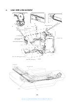
Page 25: ... 23 2 LEAD WIRE ARRANGEMENT www promelectroavtomat ru ...
Page 67: ...ULT2003D S G 3100D ULT2001N ULT2001C M3000N M3000C 11C03HF114200 www promelectroavtomat ru ...


