-12-
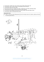
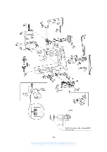
23. Remove the connector, then remove the two screws and the thread cutter unit.
24. Remove the screw and the inner rotary hook rotation prevention bracket.
25. Remove the presser bar clamp screw.
26. Remove the presser bar by lifting it from above, and the presser bar clamp and presser spring.
27. Remove the two screws, and remove the presser frame assembly.
28. Remove the presser lifting shaft by pulling it out from the back, the presser lifter and lifter.
29. Remove the screw and the thread take-up shaft.
Disassembly Point
23. Before removing the thread cutting assembly, move the thread cutter cam so that its notch faces the front
of the sewing machine (A).
www.promelectroavtomat.ru
Summary of Contents for M3000C
Page 4: ... 2 1 MECHANICAL CHART EMBROIDERY UNIT MECHANISM www promelectroavtomat ru ...
Page 6: ... 4 3 ELECTRONIC PARTS ARRANGEMENT CHART www promelectroavtomat ru ...
Page 13: ... 11 www promelectroavtomat ru ...
Page 17: ... 15 www promelectroavtomat ru ...
Page 19: ... 17 www promelectroavtomat ru ...
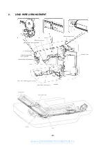
Page 25: ... 23 2 LEAD WIRE ARRANGEMENT www promelectroavtomat ru ...
Page 67: ...ULT2003D S G 3100D ULT2001N ULT2001C M3000N M3000C 11C03HF114200 www promelectroavtomat ru ...


