-13-
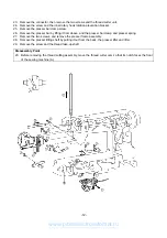
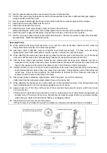
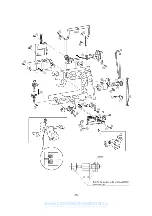
30. Remove the 4 screws from the horizontal feed shaft supporter and the feed adjustment unit shaft supporter.
Remove the horizontal feed assembly.
31. Pull out the motor connector. Remove the 3 screws and the power supply unit.
32. Remove the motor belt and the 2 screws and the main motor.
(When removing the motor from the motor holder, remove the motor fan then remove the 2 screws.)
33. Remove the four screws and the handle.
34. Remove the screw and the tension pulley holder.
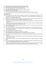
35. Remove the two screws securing the upper shaft metal, the upper shaft assembly and the timing belt.
36. Remove screw and the outer rotary hook assembly .
37. Remove the both presser plate screws. Remove the lower shaft assembly and the timing belt.
Disassembly Points
30. Before removing the horizontal feed assembly, remove the feed bar tension spring (C).
www.promelectroavtomat.ru
Summary of Contents for M3000C
Page 4: ... 2 1 MECHANICAL CHART EMBROIDERY UNIT MECHANISM www promelectroavtomat ru ...
Page 6: ... 4 3 ELECTRONIC PARTS ARRANGEMENT CHART www promelectroavtomat ru ...
Page 13: ... 11 www promelectroavtomat ru ...
Page 17: ... 15 www promelectroavtomat ru ...
Page 19: ... 17 www promelectroavtomat ru ...
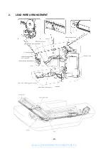
Page 25: ... 23 2 LEAD WIRE ARRANGEMENT www promelectroavtomat ru ...
Page 67: ...ULT2003D S G 3100D ULT2001N ULT2001C M3000N M3000C 11C03HF114200 www promelectroavtomat ru ...


