


-10-
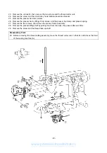
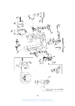
10. Remove the presser holder and needle.
11. Remove the 17 connectors, the four screws, and the main PC board.
12. Remove the screw and thread winding assembly.
13. Remove the three screws and NP base assembly.
14. Remove the two washers. Remove the 2 screws and the wire support plates. Remove the wire assembly .
15. Remove the inlet assembly connector. Then the 3 screws and base plate assembly.
16. Remove the two screws on the left. Remove the two screws and the side feed assembly.
17. Remove the two screws and the FPM holder.
18. Remove the spring, and remove the two screws. Remove the thread tension assembly.
19. Remove the screw and the needle bar supporter stud holder assembly.
20. Remove the two springs (B) and the needle bar block assembly.
21. Remove the two screws and the two cord holders.
22. Remove the three screws and the ZPM assembly.
Disassembly Points
11. To disconnect the connectors, grab the base of the connector and pull it straight out.
∗
In order to reduce the risk of static electric damage to the main PC board after it is removed from the
sewing machine, do not touch the board’s front surface and only carry it by its edges in the same way
that you hold a compact disk.
19. To remove the needle bar supporter stud holder, move it upward while removing it from the pin.
www.promelectroavtomat.ru
Summary of Contents for M3000C
Page 4: ... 2 1 MECHANICAL CHART EMBROIDERY UNIT MECHANISM www promelectroavtomat ru ...
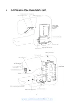
Page 6: ... 4 3 ELECTRONIC PARTS ARRANGEMENT CHART www promelectroavtomat ru ...
Page 13: ... 11 www promelectroavtomat ru ...
Page 17: ... 15 www promelectroavtomat ru ...
Page 19: ... 17 www promelectroavtomat ru ...
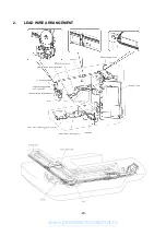
Page 25: ... 23 2 LEAD WIRE ARRANGEMENT www promelectroavtomat ru ...
Page 67: ...ULT2003D S G 3100D ULT2001N ULT2001C M3000N M3000C 11C03HF114200 www promelectroavtomat ru ...