background image

21


5.6.3


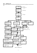
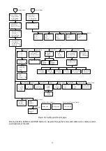
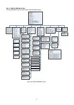
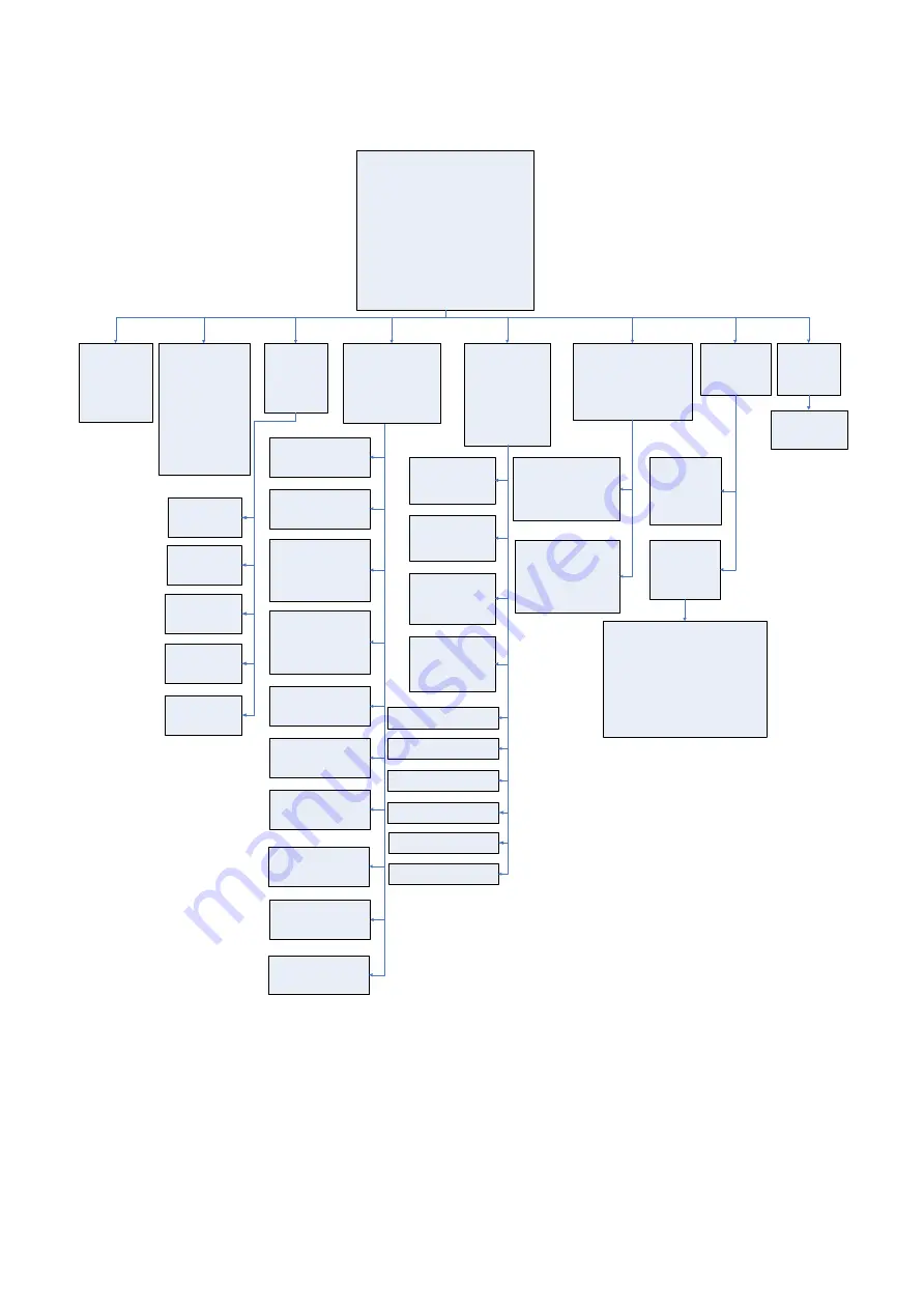
RS232/USB Menu Tree 

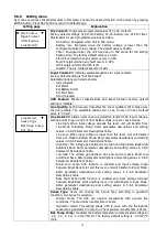
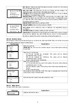
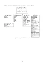
The complete Menu Tree is shown below with all default values.   


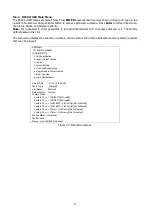
UPS Model: Outdoor2000

ID 92611308100015

[0-MAIN MENU]

  1 Unit Specification

  2 Input / Output Values

  3 Control

  4 System Setting

  5 Line Conditioning Setup

  6 Programmable Contacts Setup

  7 Event Log View

  8 Login Administrator

Date & Time    : 13-09-13, 18:25:26

Sense Type     : [Normal]

Line Status    : Normal

Output Status  : Normal

Contact Status :

  Contact C1 ==> [ON BATT]/[Not Activated]

  Contact C2 ==> [ON BATT]/[Not Activated]

  Contact C3 ==> [LOW BATT : 46.0 Volts]/[Not Activated]

  Contact C4 ==> [LOW BATT : 46.0 Volts]/[Not Activated]

  Contact C5 ==> [Timer : 2.00 Hours]/[Not Activated]

  Contact C6 ==> [Timer : 2.00 Hours]/[Not Activated]

Ext.Fan Status : [Activated]

Faults : None

Alarms : BTS Disconnect

[0-MAIN MENU]

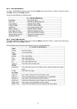
  [1-Unit Specification]

    Unit Model        Outdoor2000

    Unit Freq             60   Hertz

    Output Voltage   120  Volts

    Output VA           2000 VA

    Battery Voltage  48   Volts

    Max Chgr Current 10.0 A

    Panel Firmware Ver 00.26

    Main  Firmware Ver 00.31

    Hardware Ver 00.02

[0-MAIN MENU]

  [2-INPUT/OUPUT VALUES]

    Input:-

      Voltage     000.0 Vac

      Freq        00.0  Hz

    Output:-

      Voltage     119.2 Vac

      Freq          50.0  Hz

      Power       0000  Watt

      VA          0000  VA

      Load Per    000   %

    Battery:-

      Temperature 25    Deg C

      Voltage     46.62 Vdc

    Evt-Timer

      INV EVENT   00003

      INV Timer   0000  Hours 30 Mins

      Boost EVENT 00000

      Boost Timer 0000  Hours 00 Mins

      Buck EVENT  00000

      Buck Timer  0000  Hours 00 Mins

[0-MAIN MENU]

  [3-Control]

    30) Self Test

    31) Dry Contact Test

    32) Ext Fan Test

    33) Ups Output

    34) Event/Timer Reset

[0-MAIN MENU]

  [4-SYSTEM SETTING]

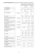
    40) Ext Fan On By Temperature

    41) Battery Low Voltage

    42) Charging Current

    43) Battery Temperature Compensation

    44) Test Timer

    45) Backup Timer

    46) Set To Default UPS

    47) Set Date

    48) Set Time

    49) Change Password

[0-MAIN MENU]

  [5-LINE CONDITIONING SETUP]

    50) Buck  function

    51) Boost function

    52) Sense Type

    53) Line Qualify Time

    54) High Limit [152] Vac

    55) Low Limit  [088] Vac

    56) Boost Low  [102] Vac

    57) Buck High  [128] Vac

    58) High Gap   [005] Vac

    59) Low Gap    [005] Vac

     *) High back  [147] Vac

     *) Low back   [093] Vac

     *) Boost back [107] Vac

     *) Buck back  [123] Vac

[0-MAIN MENU]

  [6-PROGRAMMABLE CONTACTS SETUP]

    60) Contact C1 = [ON BATT]

    61) Contact C2 = [ON BATT]

    62) Contact C3 = [LOW BATT : 46 Volts]

    63) Contact C4 = [LOW BATT : 46 Volts]

    64) Contact C5 = [Timer : 2.00 Hours]

    65) Contact C6 = [Timer : 2.00 Hours]

    66) PROGRAM I/P Contact = [EXT FAN FAILED]

[0-MAIN MENU]

  [7-EVENT LOG VIEW]

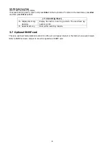
    70) Display Event Records

    71) Reset Event Log

[0-MAIN MENU]

  [7-EVENT LOG VIEW]

    [70-Display Event Records]

      0) Event #001-#050

      1) Event #051-#100

      2) Event #101-#150

      3) Event #151-#200

      >

[0-MAIN MENU]

  [5-LINE CONDITIONING SETUP]

    [51-BOOST FUNCTION]

      Current setting is [Enable]

      0) Disable

      1) Enable

      >

[0-MAIN MENU]

  [5-LINE CONDITIONING SETUP]

    [52-SENSE TYPE]

      Current setting is [Normal]

      0) Normal

      1) Generator

      >

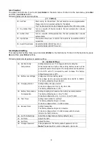
HIGH LIMIT [152]    Enter new value. (120->152)

>

[0-MAIN MENU]

  [6-PROGRAMMABLE CONTACTS SETUP]

    [60-CONTACT C1]

       Current Setting is [ON BATT]

       0) Set to [ON BATT]

       1) Set to [LOW BATT]

       2) Set to [TIMER]

       3) Set to [ALARM]

       4) Set to [FAULT]

       5) Set to [OFF]

       6) Set to [DISABLE]

       >

[0-MAIN MENU]

  [6-PROGRAMMABLE CONTACTS SETUP]

    [66-PROGRAM I/P CONTACT]

       Current Setting is [EXT FAN FAILED]

       0) Set to [USER PROGRAM IN]

       1) Set to [EXT ALARM]

       2) Set to [EXT BATT ALARM]

       3) Set to [EXT FAN FAILED]

       4) Set to [DOOR UNLOCK]

       >

[0-MAIN MENU]

  [8-Login Administrator]

    Current user is [Guest]

    Please Enter Password

    >1111

    >Success

[0-MAIN MENU]

  [4-SYSTEM SETTING]

    [40-EXT FAN ON BY TEMPERATURE]

    Current setting is [25 Deg C]

    Enter new value. (20->50)

    >

[0-MAIN MENU]

  [4-SYSTEM SETTING]

    [41-BAT LOW VOLTAGE]

    Current setting is [47.5 Volts]

    Enter new value. (42.0->55.0)

    >

[0-MAIN MENU]

  [4-SYSTEM SETTING]

    [42-Charging Current]

    Current setting is [10 Ampers]

    0) Set to 2  Ampers

    1) Set to 4  Ampers

    2) Set to 6  Ampers

    3) Set to 8  Ampers

    4) Set to 10 Ampers

    >

[0-MAIN MENU]

  [4-SYSTEM SETTING]

    [43-Battery Temperature Compensation]

    Current setting is [-3.0 mv/Deg C/Cell]

    0) Set to -2.5 mv/Deg C/Cell

    1) Set to -3.0 mv/Deg C/Cell

    2) Set to -3.5 mv/Deg C/Cell

    3) Set to -4.0 mv/Deg C/Cell

    >

[0-MAIN MENU]

  [4-SYSTEM SETTING]

    [44-Test Timer]

       Current setting is [001min]

       Enter New Value

       >

[0-MAIN MENU]

  [4-SYSTEM SETTING]

    [45-Backup Timer]

       Current setting is [08] (Unit = 0.25Hour)

       Enter New Value

       >

[0-MAIN MENU]

  [4-SYSTEM SETTING]

    [46-Set To Default UPS]

    0) No

    1) Yes

    >

[0-MAIN MENU]

  [4-SYSTEM SETTING]

    [47-Set Date]

     Current Date is [13-09-13]

     Enter new value (**-**-**)

     >

[0-MAIN MENU]

  [4-SYSTEM SETTING]

    [48-Set Time]

     Current Time is [18:38:54]

     Enter new value (**:**:**)

     >

[0-MAIN MENU]

  [4-SYSTEM SETTING]

    [49-Change Password]

     Please Enter New Password:0000-9999

     >

 Self Test

    0) Stop

    1) Start

    >

Dry Contact Test

    0) Off

    1) On

    2) Cancel

    >

 Ext FAN Test

    0) Off

    1) On

    2) Cancel

    >

    Reset Event/TM

    0) No

    1) Yes

    >

Ups Output

    0) Off

    1) On

    >

[0-MAIN MENU]

  [5-LINE CONDITIONING SETUP]

    [50-Buck Function]

      Current setting is [Enable]

      0) Disable

      1) Enable

      >

[0-MAIN MENU]

  [5-LINE CONDITIONING SETUP]

    [53-Line Qualify Time]

      Current setting is [03 Seconds]

      0) Set to 3  seconds

      1) Set to 10 seconds

      2) Set to 30 seconds

      >

 Low Limit [088]    Enter new value. (088->120)

  >

 Boost Low [102]    Enter new value. (096->120)

 >

 Buck High [128]    Enter new value. (120->144)

 >

 High Gap [005]    Enter New Value. (003->007)

 >

 Low Gap [005]    Enter New Value. (003->007)

 >

[0-MAIN MENU]

  [7-EVENT LOG VIEW]

    70) Display Event Records

    71) Reset Event Log

71

Success

    Reset Event Log

    0) No

    1) Yes

    >1

[0-MAIN MENU]

  [7-EVENT LOG VIEW]

    [70-Display Event Records]

      0) Event #001-#050

      1) Event #051-#100

      2) Event #101-#150

      3) Event #151-#200

      >0

001.2013-09-05 21:20:26 In Bat Mode Warning:Drycontact1 :[ON BAT]

002.2013-09-05 21:23:28 In Normal   Warning:Line Fail

003.2013-09-05 21:23:31 In Bat Mode Warning:Drycontact1 :[ON BAT]

004.2013-09-05 21:24:27 In Off Mode Warning:Line Fail

005.2013-09-06 11:11:55 In Off Mode Warning:Line Fail

006.2013-09-06 11:11:57 In Bat Mode Warning:Drycontact1 :[ON BAT]

007.2013-09-06 11:33:09 In Off Mode Warning:Line Fail

008.2013-09-06 12:27:54 In Off Mode Warning:Line Fail

009.2013-09-06 12:27:54 In Off Mode Warning:Bat Temp High

010.2013-09-06 12:30:10 In Off Mode Warning:Fan Fault

[0-MAIN MENU]

  [8-Login Administrator]

    Current user is [Administrator]

    Success To Access!

    >


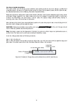
Figure 19: RS232/USB Menu Tree


Summary of Contents for PRO2000LD

Page 1: ...LINE INTERACTIVE UPS User Manual OUTDOOR LINE INTERACTIVE UPS 1P 1P RACK PRO2000LD 2KVA Version 1 00 English...

Page 2: ...5 1 Switch on UPS in Line mode 9 5 2 Switch the UPS from line mode to battery mode 9 5 3 Switch from battery mode to line mode 9 5 4 Switch off procedure 9 5 5 Operation the Control panel 10 5 6 RS23...

Page 3: ...tempting any maintenance or cleaning Turning off the unit will not reduce this risk 5 CAUTION Only qualified personnel can install this device with battery 6 NEVER charge a frozen battery 7 For optimu...

Page 4: ...sts of Uninterruptible Power Supply UPS System and optional Power Transfer Switch PTS that provide backup power when the line is unqualified These components should be mounted inside an enclosure to p...

Page 5: ...Breaker This circuit breaker is a resettable protective thermal circuit breaker to protect UPS output from overload and short circuits Input Contact To activate a programmable alarm by shorting this...

Page 6: ...Three LEDs show the information of output status alarm and fault USB Connector This is used to connect the UPS to the computer for remote control and monitoring RS232 Connector A straight through DB 9...

Page 7: ...UT provides input power protection for the UPS AC Output Receptacles These receptacles are ready to use for optional battery heating pads or a PC for maintenance UPS Input Connector This UPS IN power...

Page 8: ...pare the listed parts with the items you received If the listed parts on your package does not match the items you received or any items appear damaged please immediately notify your carrier agent and...

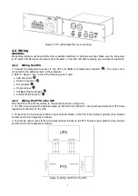
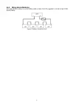
Page 9: ...following ports if used USB Connector RS 232 Connector Dry contacts Program input Intelligent Slot optional External FAN Connector 4 4 2 Wiring the PTS to the UPS Wire the PTS to the UPS according to...

Page 10: ...8 4 4 3 Wiring External Batteries Unit supports 48Vdc battery Connect all battery packs as below chart It s suggested to connect at least 100Ah capacity battery Figure 7 Battery Connection Chart...

Page 11: ...ery mode UPS will operate in battery mode if manually switch the input circuit breaker off The LCD will display Battery and output LED will flash to show the UPS is running on backup battery power 5 3...

Page 12: ...On Output is available in line mode Flashing Output is available in battery mode Off Output is not available Alarm Yellow Solid On Alarms occur in the system indicating a condition not serious enough...

Page 13: ...vEV xxxxx 13 InvTM xxxx xH 14 BukEV xxxxx 15 BukTM xxxx xH 16 BstEV xxxxx 17 BstTM xxxx xH 18 C1 Off or On C2 Off or On 19 C3 Off or On C4 Off or On 20 C5 Off or On C6 Off or On 21 MainFW xx xx 22 LCD...

Page 14: ...Time Default UPS YES NO Default UPS Setting Password xxxx Setting Password Setting OK Setting failed Setting OK Fail Display Access Denied Enter Wrong Password Display Setting menu Dry Contact Input...

Page 15: ...The unit automatically transfers to battery mode when input line power is unqualified or not present Batteries provide power to the loads SelfTest When Self Test is executed the unit will enter Batter...

Page 16: ...The number of times the unit has been in buck mode The total time duration the unit has been in buck mode since the latest reset Page 5 16 BstEV xxxxx 17 BstTM xxxx xH 18 C1 Off C2 Off 19 C3 Off C4 O...

Page 17: ...oints to go in and out from battery mode boost or buck modes Line High When input voltage exceeds this level unit will transfer from Line Mode to Battery Mode Refer parameter descriptions and setting...

Page 18: ...ssword Re entry is required if an error occurs when entering the password 5 5 10 Control menu Press SCROLL button to switch desired option in Control menu and press ENTER button to confirm new option...

Page 19: ...ow below steps to step up HyperTerminal Step 1 The path of HyperTerminal communication tool is Programs Accessories Communications HyperTerminal as shown in Figure 12 Figure 12 Hyper Terminal Selectio...

Page 20: ...will pop up COM Properties screen and select port setting as shown in Figure 15 and click OK Figure 15 COM Properties Step 5 A blank window with the entered file name will pop up Refer to Figure16 In...

Page 21: ...ill pop up as shown in Figure 17 Click on the Settings tab Select all columns as below figure and click ASCII Setup button Figure 17 ASCII Properties Screen Step 7 Set up all columns in the ASCII Setu...

Page 22: ...20 Figure 18 ASCII Setup Screen Step 8 Press Enter to go to UPS screen and access the UPS via RS232 USB communications...

Page 23: ...ER 3 Set to ALARM 4 Set to FAULT 5 Set to OFF 6 Set to DISABLE 0 MAIN MENU 6 PROGRAMMABLE CONTACTS SETUP 66 PROGRAM I P CONTACT Current Setting is EXT FAN FAILED 0 Set to USER PROGRAM IN 1 Set to EXT...

Page 24: ...us and any faults or alarms that may be present UPS Model ID 92611310100001 0 MAIN MENU 1 Unit Specification 2 Input Output Values 3 Control 4 System Setting 5 Line Conditioning Setup 6 Programmable C...

Page 25: ...ut Voltage Low Over Temperature INV Output Voltage High Contact Status Ext Fan Status Displays Fan Fault Over Temperature Battery Voltage High Fan Fault Activated Over Load Battery Voltage High Not Ac...

Page 26: ...return to the main menu press Esc and then press Enter buttons Following table lists the actual measurements of input output parameters 2 Input Output Values Input Voltage The Input voltage Freq The I...

Page 27: ...C to trigger external cooling fan When temperature is higher than setting battery power will be provided for external cooling fan The temperature can be set from 20 to 55 C with 1 C increment by each...

Page 28: ...ransformer will automatically switch to the secondary tap to buck or boost voltage 10 to keep the output voltage within acceptable range CAUTION Improperly parameter value setting can cause permanent...

Page 29: ...drops between Boost Back point and Boost Low point unit will transfer to Boost Mode only when AVR is enabled Normal to Boost DISABLE 102VAC or 216VAC 96 120VAC or 192 240Vac 57 Buck High When input vo...

Page 30: ...Enter buttons 7 Event Log View 70 Display Event Log Records Display the history event log records The maximum log number is 200 71 Reset Event Log Clear all the event log records 5 7 Optional SNMP car...

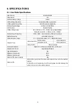
Page 31: ...to detection 55Hz as boundary Default frequency Last utility frequency Utility frequency range 47 53 Hz 50Hz mode 57 63Hz 60Hz mode Transfer Time UPS without PTS Normal mode 12ms maximum Generator mod...

Page 32: ...fficiency 90 No Load Power Consumption 28W 48Vdc THD Bat mode 3 Full resistive load Load crest factor 3 1 rated load Overload protection 5s 125 150 load 60s 110 125 load Output short circuit protectio...

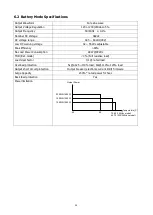
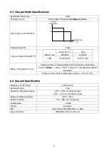
Page 33: ...protection IEEE ANSI C 62 41 2KV L N Appropriate battery type AGM Charging Current 2Amp 4Amp 6Amp 8Amp 10Amp adjustable Max charger current limitation 10 8 Temperature C Charger Current A 40 50 Charg...

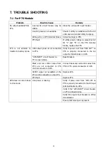
Page 34: ...fy if power cord from UPS OUT on PTS is properly connected to the AC output terminal blocks on UPS UPS INPUT circuit breaker on PTS is open status Reset breaker Black and red control wires from PTS ar...

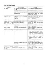
Page 35: ...breaker Battery is not fully charged Recharge the battery and then test discharge time Dead battery Replace with new batteries UPS fault Return to repair center Alarm LED is lit Abnormal conditions ar...

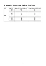
Page 36: ...Back up Time Table Model Load VA Backup Time 48Vdc 100Ah min Backup Time 48Vdc 200Ah min 2KVA 200 1581 3161 400 751 1581 600 491 1054 800 331 760 1000 268 615 1200 221 508 1400 172 387 1600 136 335 1...

Page 37: ...ERS INDONESIA Office PT PROLiNK INTIDATA NUSANTARA Walk In Jl Cideng Barat No 79 Jakarta Pusat 10150 Indonesia Email Support support id prolink2u com MALAYSIA Office FIDA SYSTEMS M SDN BHD Walk In 29...

Reviews: