7
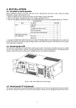
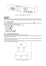
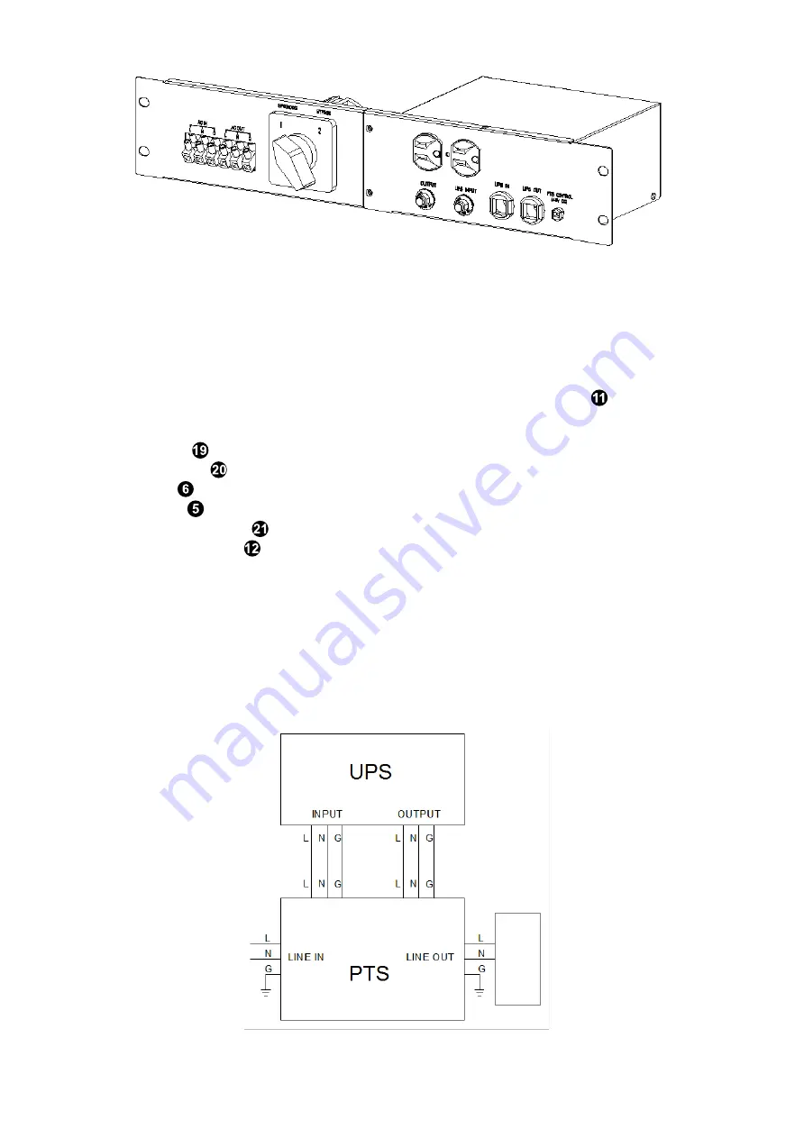
Figure 5: PTS with Bracket for rack mounting
4.4
Wiring
WARNING!
All electrical wiring must be performed by a qualified electrician or trained personnel. Make sure the line power
is off. Switch off all input and output circuit breakers on the UPS unit before making any electrical connections.
4.4.1
Wiring the UPS
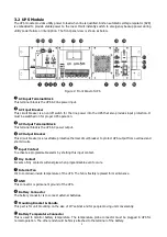
1. Connect the temperature sensor to the UPS unit (Battery Temperature connector
). The other end is
connected to the batteries later in the procedure.
2. Refer to Figure 1 & 2, connect the following ports if used.
•
USB Connector
.
•
RS-232 Connector
.
•
Dry contacts
.
•
Program input
.
•
Intelligent Slot (optional)
.
•
External FAN Connector
.
4.4.2
Wiring the PTS to the UPS
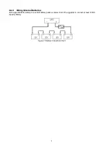
Wire the PTS to the UPS according to the schematic shown in Figure 6.
1. The PTS is pre-wired with 2 cables marked as “UPS IN” and “UPS OUT”. Connect these cables from PTS to the
respective connectors on the UPS.
2. Connect the AC input wires to the AC input terminal blocks on the PTS. Ensure proper polarity (Line, Neutral
and Ground to the respective terminal).
3. Connect AC output wires to the AC output terminal blocks on the PTS. Ensure proper polarity (Line, Neutral
and Ground to the respective terminal).
Figure 6: Wiring the PTS to the UPS

