


8611311
180 MULTI-PROCESS MIG-ARC-TIG WELDER
V1.0
14
For technical questions call 1-800-665-8685
INSTALLATION AND SET UP FOR DC TIG WELDING
The set up described is for DC Electrode Positive (DCEP).
1. Connect the TIG torch to the Euro connection socket and tighten the connection.
2. Connect ground lead to the negative outlet socket.
3. Connect the weld power lead (J) to positive output socket (I).
4. Turn the power source on and select the TIG function with the welding mode knob.
5. Set torch operation to 2T or 4T.
• 2T - Press and hold the trigger to start the gas, touch the tungsten wire to the work and
pull away to initiate the arc. Release the trigger to stop. [See Lift Arc Ignition for TIG
(Tungsten Inert Gas) Welding.]
• 4T - Press the trigger to start the gas, touch the tungsten to the workpiece, pull away to
initiate the arc, then release the trigger. Press and release the trigger to stop the gas
and arc.
6. Connect the gas hose to the regulator then connect the regulator to the gas cylinder
Connect the other end of the gas hose to the gas inlet (L) on the rear of the welding
machine. Check for gas leaks.
CHECK FOR GAS LEAKAGE
Check for gas leakage after each time the welding unit is set up for TIG welding and at
regular intervals.
The recommended procedure is as follows:
1. Connect the regulator and gas hose assembly, then tighten all connectors and clamps.
2. Slowly open the cylinder valve.
3. Set the flow rate on the regulator to approximately 15 to 25 CFH.
4. Close the cylinder valve and pay attention to the needle indicator on the regulator’s
pressure gauge. If the needle drops away towards zero there is a gas leak.
Sometimes a gas leak can be slow and to identify. Leave the gas pressure in the regulator
and line for an extended time period. Perform the test as above, but reduce the flow rate to
16 to 21 CFH. Close the cylinder valve and check after a minimum of 15 minutes.
5. After confirming there is a loss of gas, check all connectors and clamps for leakage by
brushing or spraying with soapy water. Bubbles will appear at the leakage point.
6. Tighten clamps or fittings to eliminate gas leakage. Replace the clamps and fittings if this
fails to solve the problem.
WIRE INSTALLATION AND SET UP
The correct installation of the wire spool and the wire into the wire feed unit is critical to
achieving an even and consistent wire feed. Poor set up of the wire into the wire feeder is a
major cause of fault with MIG welding machines. The guide below will assist in the correct setup
of your wire feeder.
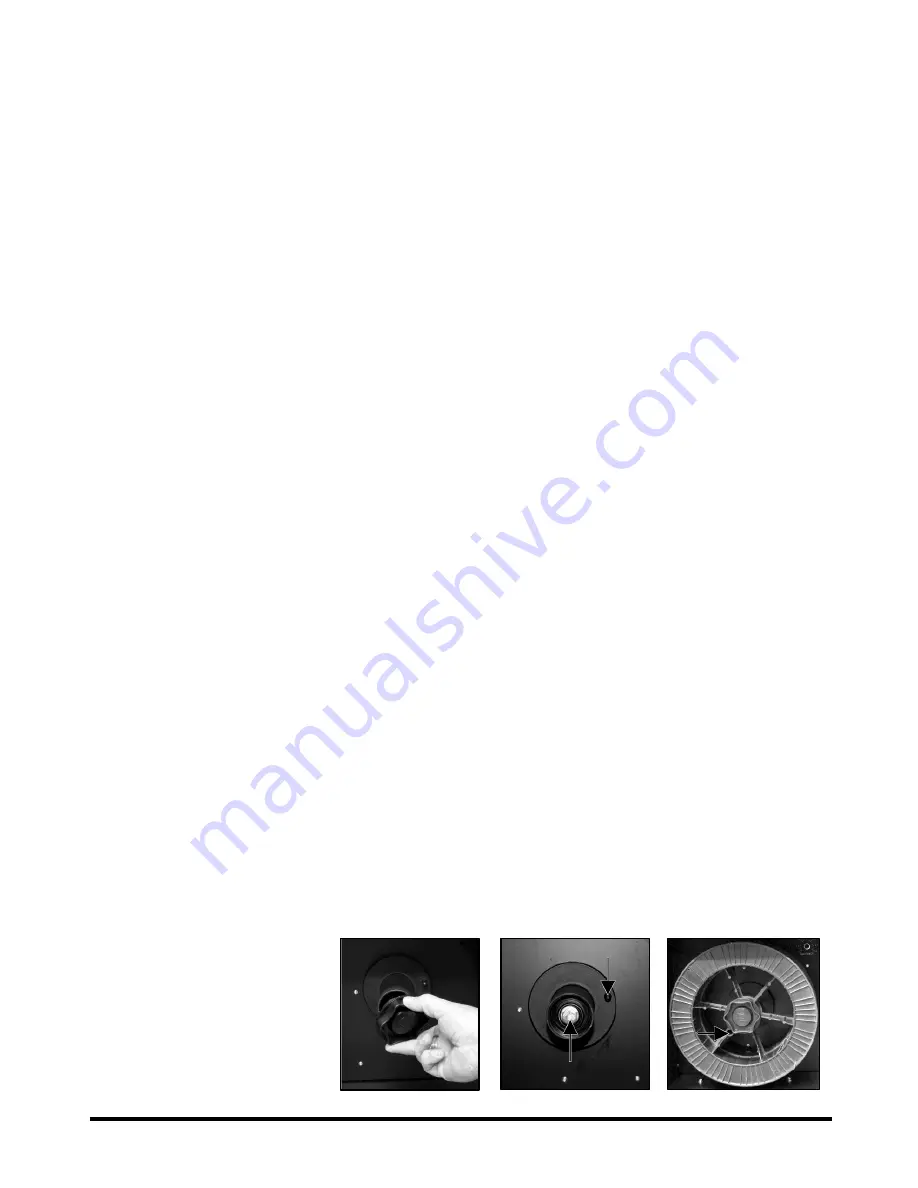
1. Remove the spool
retaining nut (Fig 8). The
spool retaining nut is left
hand threaded.
2. Note the tension spring
adjuster (Fig. 9-1) and spool
locating pin (Fig. 9-2).
Fig. 8
Fig. 9
Fig. 10
9-2
9-1


