8611311
180 MULTI-PROCESS MIG-ARC-TIG WELDER
V1.0
12
For technical questions call 1-800-665-8685
ASSEMBLY & INSTALLATION
Letter references in parenthesis (A) refer to the included Identification Key. Dashed numbers in
parenthesis (Fig. 1-1) refer to specific point of an illustration or image
DUAL VOLTAGE
TYPE
INPUT
RATED CURRENT
OUTPUT
DUTY CYCLE
X
I2
U2
ARC
115V-20A
27.5A
10A/20.4V
~
100A/24V
25%
100A
24V
60%
65A
22.6V
100%
50A
22V
230V
30A
10A/20.4V
~
160A/26.4V
25%
160A
26.4V
60%
103A
24.1V
100%
80A
23.6V
MIG
115V-15A
21.4A
30A/15.5V
~
100A/19V
25%
100A
19V
60%
65A
17.3V
100%
50A
16.5V
230V
30.2A
30A/15.5V
~
180A/21.5V
25%
180A
23V
60%
116A
19.8V
100%
90A
18.5V
TIG
115V
21.4A
10A/10.4V
~
100A/14V
25%
110A
14V
60%
65A
12.6V
100%
50A
12V
230V
22.6A
10A/10.4V
~
180A/17.2V
25%
180A
17.2V
60%
116A
14.6V
100%
90A
13.6V
X = Duty cycle%age
I2 = Welding Current
U2 = Secondary Voltage with Welding Current I2
INSTALLATION SET UP FOR ARC (STICK) WELDING
Please install the machine strictly according to the following steps.
POWER REQUIREMENTS
The power cord supplied with this welding unit is designed to handle the maximum power
required (see Specifications). Refer to the welding unit’s data plate and ensure the power
supply can meet those requirements.
CONNECTING THE POWER LEADS
1. Connection of Output Cables - An electrode may require either a positive or a negative
charge for optimum results. Connect the electrode holder to the Positive Outlet Socket (I)
or Negative Outlet Socket (G) based on the
electrode manufacturer’s information for
the correct polarity set up.
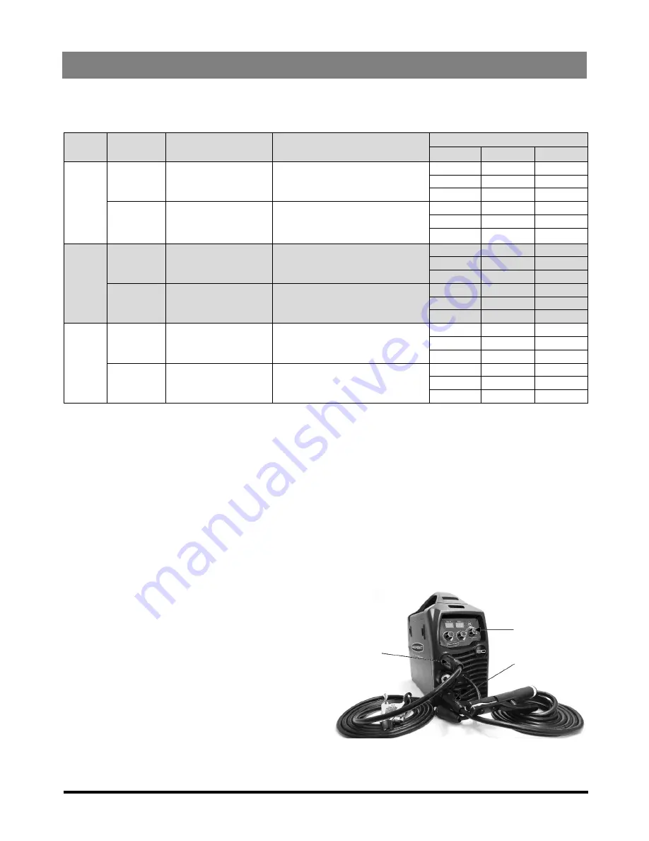
Figure 4 represents the default
configuration for ARC with the ground lead
connected to the positive lead (Fig. 4-1)
and the electrode holder connected to the
negative lead (Fig. 4-2).
2. Turn the power source on and select the
ARC function with the welding mode knob
(Fig. 4-3).
Fig. 4
4-3
4-1
4-2
Table 1


