11
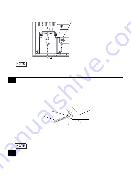
(3) Remove the screws from the two (2) terminals (L,N) and FG (Frame Ground)
Terminal, position the Ring Terminals and reattach the screws. (Check each wire to
make sure the connections are correct)
(4) Reattach the Terminal Strip’s clear plastic cover.
USB Cable Clamp Attachment Procedure
Installation to USB cable
(1) Connect the USB cable to the connector.
(2) Tighten the clamp until the cable is secured in place and insert the convex of cable
clamp into the USB fixing hole to fix both as shown in the following figure.
USB Cable Clamp Removal Feature
(1) Push in the cable clamp's stopper with a standard flat-blade screwdriver until the
cable clamp is unlocked, and remove it.
(2) Disconnect the USB cable.
Please pay special attention to the following instructions when connecting the power cord
terminals to the FP unit.
• If the power supply voltage exceeds the FP unit’s specified range, connect a voltage
transformer.
• The torque required to tighten these screws are as follows:
Terminal Block: 0.5 to 0.6N•m.
FG (Frame Ground) Terminal: 0.6 to 0.7 N•m.
7
Using the USB Cable Clamp
• If the stopper will not move, press on <A> (shown in the figure) to
free the clamp from the clamp holder.
8
Power Supply Cautions
DON’T
CONNECT
FG (Frame Ground) Terminal
USB cable
USB Cable Clamp
Stopper
<A>
USB fixing hole


