background image


19 


before continuing. If necessary, adjust the 45

o

 further to maximise the size of the peak. 

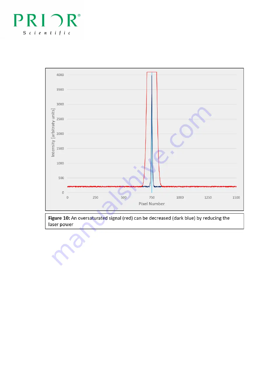
After maximising the size of the peak, if the peak crosses the top of the graph reduce 

the laser power until the top of the peak is visible (Fig. 10).  


Make this peak as sharp as possible by rotating the digipot. It is optimal for the peak to fill 

almost the entire y-axis of the graph. See section 4.3.3 for full details.  

Click the Auto Set Centre button, and click ‘Yes’ in the following pop-up box. This will set the 

centre of the PureFocus850 sensor, which is used to positively verify whether the sample is in 

focus.  

Check that a peak is visible with each of the other objectives, before returning to the highest 

magnification objective.  


Summary of Contents for PureFocus850

Page 1: ...2 2 Status Released Aims This document contains an in depth guide to the PureFocus850 including a full installation walkthrough for both automatic and manual setup The troubleshooting section has bee...

Page 2: ...packing your system 7 3 4 Installing your PF850 mounting kit 10 3 5 Installing the PF850 10 3 6 PF850 Controller Guide 11 Section 4 Optical Alignment 13 4 1 Aligning the PF850 with the optical path 13...

Page 3: ...0 2 Laser signal is too high or too low in setup mode 57 10 3 Additional peaks are visible in setup mode 58 10 4 Background signal in setup mode is high or uneven 59 10 5 No or imbalanced error value...

Page 4: ...ot poke inside the open aperture in the base plate of the unit There are delicate optical components which are easily damaged if touched WARNING This unit emits non visible laser radiation at 850 nm f...

Page 5: ...f sample types with a reflective surface including permanently mounted glass slides live specimens in aqueous solution metallurgical semiconductors and other samples with multiple reflective layers Th...

Page 6: ...specimen resides This allows for continuously variable offsets to be added This is especially useful when dealing with biological samples where the specimen will reside under a coverslip which has a...

Page 7: ...he line sensor C and D which aid in operation C is simply the value of the centre pixel D is the summation of pixels across an arbitrary section of the sensor which is settable to any range of pixels...

Page 8: ...orking with transmitted light illumination PureFocus could be susceptible to illumination light reaching its sensor In this case it is better to set the illumination light source to the lowest brightn...

Page 9: ...tall the PureFocus850 Part Number Description LF335 Flange set for Olympus upright microscopes LF320 Flange set for Nikon upright microscopes LF310 Flange set for Leica upright microscopes contact Pri...

Page 10: ...contrast DIC imaging Mount the PF850 head between the nosepiece and any DIC optics Phase objectives are compatible with the PF850 Line mode For upright microscopes mount the PF850 at 30 60 degrees wi...

Page 11: ...ontroller and start the PureFocus850 GUI Reset the PureFocus to factor defaults by clicking Parameters Factory Reset This will close the GUI 3 6 PF850 Controller Guide The controller complements the G...

Page 12: ...gipot controls the offset lens mechanics Moving the offset lens will cause a change in focus position in real time as the servo causes the focus motor to move a distance corresponding to the increase...

Page 13: ...the nosepiece to place the alignment target into the optical path Place the PF300 alignment camera onto the microscope stage using an appropriate sample holder Connect the camera to the PC via the US...

Page 14: ...e signal is clearly visible but not reflecting off the target Typical values for this are 400 1000 however this varies between systems and values outside of this range are acceptable if required To se...

Page 15: ...sing the 45o screw adjust the lateral position of the laser line so that it aligns over the centre of the target Fig 7 Using the 0o screw adjust the position of the laser line so that equal halves of...

Page 16: ...sely mimics wafers When using biological samples on microscopes without diascopic illumination Prior Scientific recommends this sample for ease of use Please note that large increases in laser power m...

Page 17: ...The blue line which indicates the pinhole centre will move to the middle of the peak Half of the total signal will be on the left side of the line and other half will be on the right 4 3 2 Sensor cen...

Page 18: ...N FOC mode to achieve focus Click Setup which will open a graph that indicates the laser intensity over the PureFocus850 sensor Adjust focus until a peak appears in the signal At this stage the peak m...

Page 19: ...p as possible by rotating the digipot It is optimal for the peak to fill almost the entire y axis of the graph See section 4 3 3 for full details Click the Auto Set Centre button and click Yes in the...

Page 20: ...Auto Set Centre function If the calculated centre of the sensor does not correlate with the peak go to the pinhole submenu and reduce the pinhole width in order to exclude these features Please refer...

Page 21: ...de screw has considerable tolerance built in so expect to undertake a large number of screw rotations during this step Once the blade is suitably positioned take the opportunity to adjust the focus an...

Page 22: ...ck Yes in the following pop up to apply this background setting to all objectives Signal below the background threshold will be removed from the setup graph Fig 13 Go to the parameters submenu and cli...

Page 23: ...15 pin D connector cable Switch the controller back on and restart the GUI The parameters set during optical alignment do not need to be recalculated if they were saved to the controller as mentioned...

Page 24: ...Upright Towards sample PID Negative Mode Non inverted Inverted Away from sample PID Negative Mode Non inverted Inverted Towards sample PID Positive Mode Inverted The aim of this procedure is to config...

Page 25: ...nfigure your system such that clicking step up causes the distance between the sample and objective to increase Section 6 Autofocus Parameter Setup 6 1 Installation Review Sections 3 4 and 5 are only...

Page 26: ...mple Suggested Objective Option 10x Stepper motor fixed slide 10x 0 17 apo 0 40 fixed slide 10x Stepper motor wafer 10x M achro 0 25 materials 20x Stepper motor fixed slide 20x 0 17 apo 0 75 fixed sli...

Page 27: ...e Typical offset values are shown for both biological and materials samples at various magnifications in the table below Achieving values outside of the given range may be as a result of identificatio...

Page 28: ...3 4 Note however that higher magnification objectives may not allow enough laser signal to operate the PureFocus850 If low peak maximums are already apparent at 5 20x magnification or no peak can be i...

Page 29: ...quired By aligning the peak maximum with the pinhole centre the required offset value has been calculated If the peak maximum crosses the top of the y axis of the graph reduce the laser power until th...

Page 30: ...Troubleshooting 6 3 4 Checking error swing Error swing is essential for operation of the PureFocus850 The speed and magnitude of swing contribute to the focus recovery range and focus stability Error...

Page 31: ...or signal maxima either side of focus 0 25 No visible error swing either side of focus Extremely rapid increase of error value followed by an immediate decrease to zero over a small Z axis movement 6...

Page 32: ...s often in the form of a large peak located away from the pinhole centre reduce the pinhole half width in the pinhole submenu such that the signal is removed from the pinhole boundaries This will excl...

Page 33: ...m that allows the PureFocus850 to maintain focus on the sample The magnitude of the proportional P integral I and derivative D gains define the rate at which the PureFocus850 recovers sample focus and...

Page 34: ...xt section If the rate of recovery is slow and the focus is stable the the P gain value can be increased Move the sample back out of focus in MAN FOC mode increase the value in by 10 and then reactiva...

Page 35: ...by a factor of two until the image becomes stable If focus on the sample cannot be held stably with any parameters refer to Section 10 Troubleshooting When the image is stable switch the controller in...

Page 36: ...perfectly in focus 6 7 Saving offset values A default offset value must be set for each objective This value will be loaded automatically when that objective is selected Go to the offsets submenu in...

Page 37: ...es in this section are not strictly required for operation of the PureFocus850 They can however be used to enhance performance enable the use of non traditional samples or as triggers in a customised...

Page 38: ...e refer to section 6 3 2 Click on Setup in the main PureFocus850 GUI A signal should be present at the pinhole centre Click on Laser in the main PureFocus850 GUI Review the setup graph Adjust the lase...

Page 39: ...when compared to others in the objective set Mouse over the background signal to determine an approximate value which will be displayed as the Y coordinate underneath the setup graph Increase the ave...

Page 40: ...gnal Decreasing the width of the pinhole helps to remove unwanted signals from the error value calculation but can also limit the focus recapture range if set too narrow The aim of section 7 is findin...

Page 41: ...n in the focus flag section of the Flags submenu If focus stability is still insufficient after switching on the interrupt function the error parameter can be increased to inactivate the servo at a hi...

Page 42: ...ide the pinhole on the setup graph Set the Lower threshold box to be this value plus 100 If no significant background signals are observable set the Lower threshold to 500 This threshold can be increa...

Page 43: ...o MAN mode whenever the sample flag is not active Move the sample back under the objective Switch the controller into SRV mode and scan the sample ensuring that focus is maintained If the sample flag...

Page 44: ...e flag will deactivate turn grey and the autofocus servo will also deactivate Note that the servo will reactivate if the error signal dictates that the PF850 drive the focus back into the defined rang...

Page 45: ...the sample It is advantageous to use from the strongest peak in the sample as focus capture range and focus stability will be enhanced however this is not mandatory Follow the objective parameter set...

Page 46: ...ma see section 6 3 4 for full details Set these as the upper and lower threshold values in the interface section of the flags submenu If the above procedure has been followed correctly the correct int...

Page 47: ...ocus In this scenario the focus error signal may be falling off and driving the sample to focus may be slow even with the maximum stable gain settings This routine will drive the Z axis towards focus...

Page 48: ...o 4095 for current objective LASER N 0 Sets laser power in range 0 to 4095 for current objective BACKGROUND a b c d BACKGROUND a b c d Sets the single pixel background levels for the 4 user regions A...

Page 49: ...ntegral gain for current objective f is integer KI F 0 Sets integral gain value for current objective f is integer KD f Query differential gain for current objective f is integer KD F KD F Sets differ...

Page 50: ...urrent objective FOCUSH h Returns the high threshold h for determining the focus state for the current objective FOCUSH h 0 Sets the high threshold h for determining the focus state for the current ob...

Page 51: ...o interrupt off i 1 servo interrupt on FOCUSI i 0 Sets the servo interrupt status see above SERVOLIMIT a p m Sets software limits a flag activation status 0 inactive 1 active p maximum positive moveme...

Page 52: ...of digipot for offset lens control n 1 100 OFL n 0 Set speed setting of digipot for offset lens control n 1 100 LENSH 0 Sends the offset lens to its home position LENSV v 0 Moves offset lens at veloc...

Page 53: ...t is 100 or the full travel range microns in piezo mode n Returns focus motion status n 0 idle n 4 moving PZ n Returns current focus position in units of 100 nm PZ n 0 Sets current focus position to n...

Page 54: ...s Returns number of microsteps per user unit for focus default value is 50 giving user units of 100 nm SSZ s 0 Sets number of microsteps per user unit for focus see above ZD d Returns sign of focus dr...

Page 55: ...or reset SAVE 0 Save all current parameters to flash backup CONFIG m 0 Sets focus actuator mode m S Stepper mode m P Piezo mode CONFIG m Returns focus actuator mode see above 9 9 Advanced commands st...

Page 56: ...when ABON 1 is used EXPOSURE e 0 Sets the line sensor exposure time in microseconds EXPOSURE e Returns the line sensor exposure time in microseconds Section 10 Troubleshooting 10 1 No laser line emit...

Page 57: ...em reinstall the head and continue with the installation procedure If the laser line is still not present contact Prior Scientific 10 2 Laser signal is too high or too low in setup mode If the laser s...

Page 58: ...ion and laser power to eliminate these peaks from the error value recalculation See section 7 2 for full details on optimising signal to noise 10 4 Background signal in setup mode is high or uneven De...

Page 59: ...ease illumination power and increase camera exposure time Similar to the above the average background can also be increased to eliminate this background signal Fig 21 If the background is high but ske...

Page 60: ...in one axis by making very small adjustments to 45o control When making this adjustment observe the sensor signal in Setup Mode to confirm that the signal size is not compromised 10 5 No or imbalance...

Page 61: ...and then decrease again when moving the focus in one direction but not the other This is caused by the signal from the second interface crossing the pinhole centre and tends to occur when the objectiv...

Page 62: ...ntroller is in SRV mode 10 9 Performance is good but the flags are inactive For many users flag setup is not required and it will not impact performance of the PureFocus850 See sections 7 3 7 4 7 6 an...

Page 63: ...y when focus is locked around the incorrect interface see section 8 1 for details Most users can use this as an indicator to manually move the sample close to optimal focus activate the servo and begi...

Page 64: ...slips may therefore prevent the use of these objectives with the PureFocus850 The PureFocus850 has a limited negative offset range typical maximum 13 000 Certain materials objectives or samples which...

Page 65: ...e aligned with the peak Typical values for the pinhole centre are between 300 and 500 but others are acceptable Lower values can be used but this restricts the size of the PureFocus850 sensor signific...

Page 66: ...then send you an RMA number which should be added to a decontamination form again located on the Prior Scientific website Do not attempt to return this unit before such a number is obtained Prior Sci...

Page 67: ...controller allows connection to either a stepper motor or a piezo actuator system which can accept an analogue 0 10V input Pin connections are as follows Pin Number Function Commments 1 Motor Phase A...

Page 68: ...s The Driver Software Installation Window shown below will alert the user that the USB driver installation is complete and the Port is ready to use When a PC is not connected to the internet and an ol...

Page 69: ...menu In the Properties window click on the Driver tab and view the Driver Date If it is older than 2016 or if the Driver Provider is not listed as FTDI see the image below a new driver needs to be in...

Page 70: ...ded to uninstall the existing FTDI drivers There is an uninstaller tool that can be accessed from http www ftdichip com Support Utilities htm CDMUninstaller From the website download the CDM Uninstall...

Page 71: ...will be populated inside the blank area Download the latest USB Driver version from http www ftdichip com Drivers VCP htm Download the proper 32 or 64 bit driver as shown below Extract all of the file...

Page 72: ...r for driver software Browse to the location of the saved Driver and click Next Windows will then update the Driver using the downloaded files A successful installation will show a new date in the USB...

Page 73: ...www prior com40 41 Software as in some instances Windows will not assign a proper COM port the first time the driver is updated At this point it is advisable to adjust the USB latency timer from the s...

Page 74: ...74 Click OK twice to save the Latency Timer change...

Reviews: