


XTR-PX2-C0006-IN004
5-2
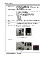
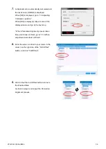
● Items to be confirmed
No.
Items
Contents
(1)
Confirming version
Check that the
value shown is other than “0.0.0.0”.
When there is no cephalometric options,
“None” is displayed in “Ceph
FPGA” and “Ceph FX3”.
(2)
Connection status of
the internal hardware
- The USB-connected part should be checked.
- The MTC and XRC should
be “OK”.
(3)
Output test
Use this area to check the laser emissions (horizontal and vertical), the
indicator LEDs, and the status LEDs
(4)
Sound test
Click “Check Speaker” to check that a sound comes out.
Adjust the volume in the control panel of the user mode.
(5)
Sensor information
Click “START” to check that the items change as below.
☑
E_ALT1
☑
E_ALT2
□
DMSW
□
DoorLock
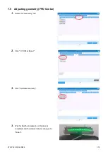
(6)
Check potentiometer
value
Click "Get PotentioVal" when the rotation arm is at the home position, and
check that the value is within the range of
“1500 to 2500”.
(7)
Motor test
Perform the test on all of the seven motors to check that all become
“SUCCESS”.
(8)
Camera image check
Move to “Cam” and check that the camera image appears.
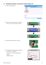
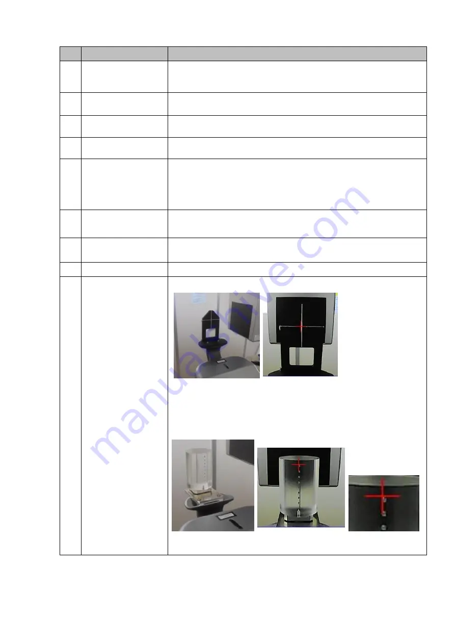
(9)
Camera position
adjustment
Attach the Camera Position Adjustment Jig.
After the step (7), click the
“Arm FrontPos” button on the upper right of the
screen to rotate the Rotation Arm.
Fit the displayed red cross mark to the center of jig and click
“OK” button.
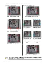
This test can be done with using Geometry phantom as below.
In the Geometry phantom, 8 small balls are implanted. We set the red
cross on the upper surface of the top ball.
* Other keys cannot be used in installation work.


