background image


22 

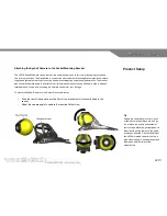
Attaching the Stick-on Mounting Pads to a helmet or other surface 


The Predator VX360 is supplied with two self adhesive Mounting Pads. These are specifically for 
enabling the user to attach the camera and mounting bracket to a helmet or other surface. 
 
The pads use a high bond, water resistant adhesive to ensure a secure platform is created for the 
mounting bracket. They are non corrosive, removable and safe for use on most surfaces, however 
some helmet manufacturer warranties can be invalidated if the surface of the shell is altered in any 
way so please check with your helmet manufacturer before attaching a patch. Predator 
Technology Ltd is in no way liable for third party warranties that may be affected directly or 
otherwise through the use of its products and accessories.  
 

o

  Choose a suitable location for the camera and mount to be placed by placing the mount at 

the desired location with camera to ensure the required camera angle can be obtained 

o

  Place a pad with the peel-off strip intact onto the area to ensure there is sufficient area for 

the pad to stick effectively 

o

  Clean the area the pad is to be stuck too to remove any moisture, dirt or grease. This will 

ensure that a much more secure bond is created. 

o

  Remove the peel-off backing and place the pad onto the prepared area. Firmly push onto 

the surface to increase the bonded strength 

 
The camera and mounting bracket can now be attached to the helmet or surface and adjusted as 
required.  


Tip 


When deciding on the best placement of 

the camera and mount on a helmet 

remember that the camera can rotate 

360 degrees so you have a great 

number of options. In our tests it has 

been found that some of the most 

watchable footage is obtained from the 

top of the helmet. 


Product Setup 


Summary of Contents for VX360

Page 1: ......

Page 2: ...itscene 3 video editing software o The Owner s Manual describes how to set up and maintain the VX360 record video and sound and transfer or display the resulting footage onto other electronic devices...

Page 3: ...tional copyright treaties You agree not to decompile disassemble modify reverse assemble reverse engineer or reduce to readable form the Software or any part thereof or create any derivative works bas...

Page 4: ...SPECIAL INDIRECT OR CONSEQUENTIAL DAMAGES OR INJURIES WHETHER RESULTING FROM THE USE MISUSE OR INABILITY TO USE THIS PRODUCT OR FROM DEFECTS IN THE PRODUCT RECORDING OF MATERIAL PROTECTED UNDER COPYR...

Page 5: ...g content Predator Technology Ltd shall in no event be liable for the loss of recordings due to malfunction or defect of this unit its accessories or recordable media PRECAUTION PVR camera and SD card...

Page 6: ...evice in water pressures over its recommended limit The penetration of water into the unit due to mishandling or misadventure by the user is not covered by the guarantee given for the unit s water res...

Page 7: ...t the connector can be inserted into the socket To secure the connection turn the locking ring in a clockwise direction being careful not to cross thread it on the socket thread o Firmly tighten the l...

Page 8: ...PVR removing the SD card changing the battery or handling any of the electrical accessories ensure that hands clothing and hair are dry to avoid accidental water splashing or transfer of moisture to v...

Page 9: ...or VX360 10 Controls 12 Charging and Installation 14 Product Setup 16 OPERATION Recording 23 Playback 28 Downloading 32 APPENDIX System Settings 33 Product Specification 35 Contents Predator Technolog...

Page 10: ...dband the VX360 keeps you hands free whilst it gets on with the job of recording the ultimate in video footage The internal Personal Video Recorder PVR is removable to allow connection to computer and...

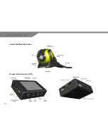
Page 11: ...11 Camera and Mounting Bracket Personal Video Recorder PVR...

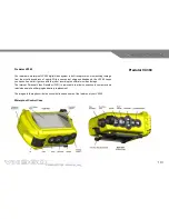
Page 12: ...will glow red when recorder is recording whether the backlight is on or not PAUSE button o Press and release to pause recording o If the LCD backlight is off press and release to turn the backlight o...

Page 13: ...SE button o Use to confirm selection on pages and menus o Use to play or pause footage in video playback mode UP DOWN button o Use to highlight menu options on pages and menus o Use to select other vi...

Page 14: ...marked DC 5V In o When charging the double LED located below the ON OFF Toggle will glow orange o When fully charged the LED will go out Unplug the PVR from the charger before switching off the mains...

Page 15: ...e PVR at the mouth of the case with the arrows on the PVR pointing in the direction of insertion and the PVR LCD screen on the same side as the LCD viewing panel on the control case o Push the PVR in...

Page 16: ...closely examining the two connectors o Check both connectors are free of sand grit hair or any other particles that could damage or otherwise compromise the waterproof seal o Mate the connectors in t...

Page 17: ...follow the instructions given below o Ensure that the fastening tape surface on the arm strap is facing upwards and the mounting bracket is also facing upwards with the protruding catch facing towards...

Page 18: ...facing down the arm o Position the strap above the bicep muscle with the mounting bracket on the top or outer side of the arm and the curved end of the arm strap and the D ring on the inner side of th...

Page 19: ...mounting bracket and slide the control case smoothly down the mounting bracket until an audible click is heard o Check the union is secure by attempting to move the control case back up the mounting b...

Page 20: ...g around its own axis providing the ultimate control over your footage To attach the Eyeball Camera to the Socket Mounting Bracket o Push the rear of the camera into the front of the bracket until it...

Page 21: ...dband on o Once the camera is pointing in the right direction push the cable at the rear of the camera down into the cable channel on the mount o Route the cable to the back of the head strap and run...

Page 22: ...essories o Choose a suitable location for the camera and mount to be placed by placing the mount at the desired location with camera to ensure the required camera angle can be obtained o Place a pad w...

Page 23: ...isplay the Predator logo followed by the PVR Main Menu Record o Press the RECORD button until a click is felt o Within a few seconds the LCD screen should display the live video feed from the camera a...

Page 24: ...automatically switched off you will need to press any control button to turn the screen back on o With the unit recording and LCD screen on press the PAUSE button until a click is felt o Within a sec...

Page 25: ...the file o If required press the STOP button twice after recording has stopped to return to the PVR main menu Power Off Once the recording has been stopped the VX360 can be switched off Do not attemp...

Page 26: ...order Settings from the Main Menu and press PLAY PAUSE to confirm the selection and enter the Recorder Settings menu o Select the Video Line in REC menu option using the UP DOWN buttons pressing the P...

Page 27: ...g info and screen prompts Off Displays minimum information on screen REC Date Time Off Visual date and time stamp on video footage is off On Visual date and time stamp on video footage is on Display L...

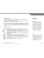
Page 28: ...o During playback use the LEFT RIGHT buttons to rewind or fast forward through the selected footage o Press the RIGHT button once for 2X twice for 4X or three times for 8X normal speed o Press the LE...

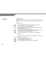
Page 29: ...e menu option o Press the RIGHT button to enter the Delete submenu o Press the UP DOWN arrow to select One or All Attention selecting All will delete all video files from the device One will delete th...

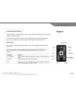
Page 30: ...out of the Control Case its functions can be controlled using the supplied PVR Remote Control Unit The majority of the buttons on the remote control unit replicate the functions of the VX360 s Contro...

Page 31: ...0 is supplied with an RCA cable for this purpose Please refer to the television manufacturer s specification to ensure your television is compatible To connect the PVR to TV o Plug the RCA cable 2 5mm...

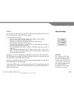
Page 32: ...advise on best practice on connecting and removing removable disk hardware Alternatively if you have the appropriate card reading device the SD card can be removed from the PVR and placed into card re...

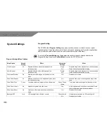
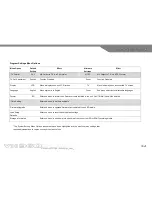
Page 33: ...ll audio after initial playback in a continuous loop Single No Repeats single audio playback in a continuous loop Stops audio playback after first play Thumbnail Preview On Displays recorded images as...

Page 34: ...on for alternative languages Format SD Enter sub menu to format the SD card currently installed in the unit CAUTION all files will be deleted Time Setting Enter sub menu to set time and date Firmware...

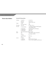
Page 35: ...40x533 16 18fps Recording Media SD and SDHC Cards up to 8GB capacity Recording capacity 50 mins per GB Recording format MPEG 4 DivX Audio Single channel integrated waterproof microphone Optical Lens 3...

Page 36: ...g measures o Re orientate or relocate the receiving antenna o Increase the separation between the equipment and receiver o Connect the equipment into an outlet that is on a different circuit than the...

Page 37: ...37...

Page 38: ...38...

Reviews: