10
11
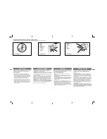
2nd Step:
The dimensions of the base must be appropriate for the dimensions of
the operator. The concrete base should be at a distance of approximately 20 mm
from the face of the gate leaf.
3rd Step:
Once the conditions are met, fully open the gate and position the
operator close to the face of the gate leaf, obeying the measurement of 50 mm
between the end of the leaf and the operator.
GATE LEAF
SIDE VIEW
CONCRETE BASE
4th Step:
Pre-align the operator to the gate, positioning the rack over the gear and
leaning the set against the gate. Then mark the fixing holes in the floor or concrete
base.
5th Step:
Drill holes for fixing, positioning the operator aligned with the gate.
Before tightening the S ¼” x 2 ½” screws, move the gate, checking that it does not
touch the operator during its route. If so occurs, back off the operator.
MARK THE FLOOR FIXING
HOLES
OPERATOR FIXING HOLES
PLACE 2 S 1/4” X 2 1/2”
SCREWS WITH S10
BUSHING
PLACE 2 S 1/4” X 2
1/2” SCREWS WITH
S10 BUSHING
MARK THE FLOOR
FIXING HOLES


