
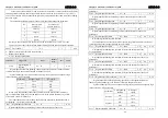

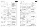


Chapter 7 Alarm
ADSD-S-S
75
too high
voltage
specifications of product
regenerative
braking fault
regenerative braking
resistance or brake
tube is invalid or not
the wiring disconnect
Please contact with
distributors or
manufacturer to solve.
braking
peak power
overload
regenerative
braking energy is
too big
checking the brake
rate load
reducing the frequency of
the
start-stop ,
Increasing
deceleration time,
reducing torque limit and
the load inertia, changing
lager power driver and
motor.
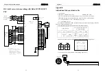
the encoder wiring
is error
checking the encoder
wiring
wiring properly, including
shielding wire
bad grounding
checking the ground
wiring
correct grounding
suffer interference
checking the sources
of interference
keeping far from the
sources of interference
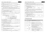
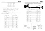
Err 15
encoder
counting
errors
encoder problem
the
number of
line and
poles
is wrong and so
as the encoders and Z
signal; encoder
damage
changing the
encoder
over the rated load
and continuously
running
checking the brake
rate load and it
thermal
reducing the load or
changing power drive
Err 16
motor
thermal
overload
encoder zero
changed
checking encoder zero
reinstalling encoder and
tuning to zero
input ac power is
too high
checking the power
voltage
make voltage accord with
specifications of product
Err 17
brake
average
power
overload
regenerative
braking energy is
too big
checking the brake
load rate
reducing the frequency of
the
start-stop ,i
ncreasing
deceleration time,
reducing torque limit and
the load inertia, changing
lager power driver and
motor.
Err 18
power
module
over the rated load
and continuously
running
checking the
current
reducing the load or
changing power drive
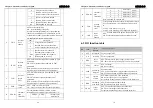
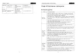
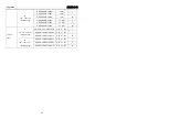
Chapter 7 Alarm
ADSD-S-S
76
overload encoder
zero
changed
checking encoder zero
reinstalling encoder and
tuning to zero
Err 20
EEPROM
error
EEPROM damage
checking on electricity
if the fault won't
disappear, please change
the drive
Err 21
logic circuit
error
control circuit fault
checking on electricity
if the fault won't
disappear, please change
the driver
current sensor and
connectors fault
checking the main
circuit
changing the drive
Err 23
AD changed
errors
AD converter and
analog amplifier
circuit fault
checking the control
circuit
changing the drive
Err 24
voltage of
control
board is low
the control circuit
LDO fault
checking the power of
the control board
changing the drive
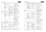
large load accident
happened
checking the load
conditions
adjusting the load
Err 29
torque
overload
alarm
parameters
L070,L071,L072
were set
unreasonable
checking the
parameters
adjusting the
parameters
encoder fault
checking encoder Z
signal
changing the
encoder
encoder cables
and connectors
fault
checking encoder
cables and connectors
changing encoder cables
and connectors
Err 30
encoder Z
signal losing
drive interface
circuit faults
checking the control
circuit
changing the drive
the encoder
wiring is errors
he
number of
line and
poles
is wrong and so
as the encoders and U
V W signal; encoder
damage
changing the
encoder
Err 31
encoder
UVW signal
error
the encoder wiring
is error
checking the encoder
wiring
wiring properly, including
shielding wire
encoder fault
checking encoder U V
W signal
changing the
encoder
Err 32
encoder
UVW signal the encoder
checking the encoder wiring properly
,
including


