


Chapter 3 Connections and Wiring
ADSD-S-S
27
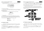
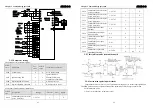
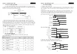
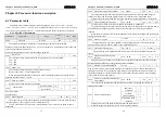
3-5 Standard connection mode
RB
RB1
W
PE
Servo
motor
Encoder
COM+
22
Red
White
Black
Green
Inscribed
braking
resistance
Tw
is
te
d-
sh
ie
ld
w
ir
e
AC220/
230V 1-phase
or 3-phase
50/60Hz
CN2
1
Ouput A phase pulse
DI1
DI2
10
DI3
19
DI4
20
DI5
21
Servo ON SON
DC12V-24V
Alarm reset
ARST
Positive drive banned
Negative drive banned
Position deviation clear
DO1
11
DO2
2
DO3
3
DOCOM
12
Servo ready RDY
Servo alarm ALM
Magnetic brake
BRK
DO common port
PULS+
13
PULS-
4
SIGN+
14
SIGN-
5
Position
instruction PULS
Position
instruction SIGN
OA+
9
OA-
18
OB+
23
OB-
15
OZ+
17
OZ-
16
A
B
Z
CZ
26
GND
24
Z signal output
open collector
Encoder signals
ground
PE
Metallic shell
5
A+
10
A-
4
B+
9
B-
3
Z+
8
Z-
2
U+
7
U-
1
1
V+
6
V-
12
W+
11
W-
13
+5V
14
GND
15
PE
CN1
Note:
1.Each digital signal
output interface is
software programmable
.The chart shows is the
factory default value
setting it can meet
general service , users
can according to what
they need to modify.
2.Motor power line and
Encoder line wring refer
to appendix
Ouput B phase pulse
Ouput Z phase pulse
Signals ground
Metallic shell
CLR
CWL
CCWL
T
S
R
MCCB
ADSD-S-S
CONTROL
MC
L1
L2
V
U
Chapter 3 Connections and Wiring
ADSD-S-S
28
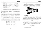
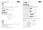
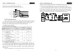
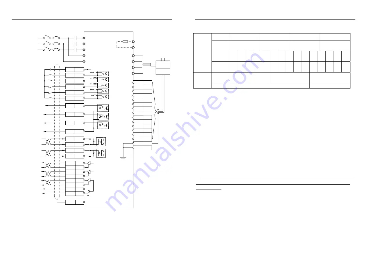
3-6 Motor wiring
Wiring U
V
W
PE
Motor
wiring
socket
Socket
no.
2 3 4 1
Signal
5
V
0
V
A
+
A
-
B
+
B
-
Z
+
Z
-
U
+
U
-
V
+
V
-
W
+
W
-
P
E
Encoder
socket
Socket
no.
2 3 4 7 5 8 6 9 10
13
11
14 12 15 1
Socket
no.
1 2 3
Break
unit
Power
24VDC (-15%~+10%)
PE
Note: the above the leads of the table is defined as the definition of motor, please refer to appendix
of wiring according to actual hookup connection in actual. Need to pay attention to motor and drive
motor wiring sequence.
3-7 Wiring note
1.Ensure control of main loop of the above components ark (such as transformer, PLC, servo
controller etc requires grounded, attention circuit breaker don't need grounded) grounding is good,
Use short and thick grounding lines connected to the public by site or grounding bus line . Connect
to any control servo control equipment (such as PLC) to its total land, also want to use short and
thick wire grounded.
2.The first, try to avoid strength wire close parallel laying, reduce cross installation .If the control
cable and power cable crossed, should as far as possible make them by Angle of 90 degrees to
cross .Weak electric signal must use the shielded wire, when the interference of electromagnetic
induction larger, appropriate with two grounded.
3.
With cable connection control of the matters needing attentions
:
①
Control of the cable with the best shielded cable; Drive motor ground wire to a good access
to the earth; shielded wire for control lines and encoder lines must doubly terminated in the
socket housing.
②
Analog signals and digital signal transmission cable should be separate shielded and gone line;
③
The analog signal transmission lines and low voltage digital signal lines should use double
shielded twisted-pair cable, and also use single shielded twisted-pair cable
.
④
Signal lines line from one side of the ark into electricity only, signal cable shielding layer double
end grounded, without impact on the operation and installation conditions, the signal cable should be
avoid too long.
⑤
Don't let 24 VDC, 5 VDC and 220 VAC share the same signal cable conduit.


