


Chapter 3 Connections and Wiring
ADSD-S-S
21
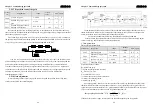
4.7K
DI1
DI2
4.7K
COM+
DC12V-24V
Servo drive
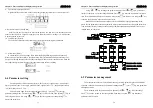
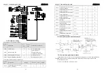
C1-2: Open collector triode
4.7K
DI1
DI2
4.7K
COM+
DC12V-24V
Servo drive
0V
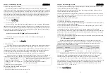
3-4-2 Output switching interface
Output switching interface (C2)
The output circuit adopts Darlington photoelectric coupler, and connects with relays and
photoelectric coupler. Safety information:
※
Power supply by users
,
If the power supply is wrong connection, can lead to drive damage.
※
The external power supply is biggest 25 V, output maximum current is 50 mA , 3 road total
current no more than 100 mA
.
※
When using inductive load such as relays, need to join diode and inductive load in parallel, if
the reverse polarity diode that can lead to drive damage.
※
Turn on, about 1 V pressure drop, can't meet the TTL low level requirements, so can't connect
with TTL circuit directly.
Chapter 3 Connections and Wiring
ADSD-S-S
22
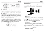
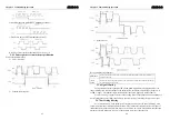
C2-1: Relay
DOCOM
DO1
DC12V-24V
Servo drive
0V
Relay
The largest output50mA
★
Freewheeling diode must be plus
DOCOM
DO1
DC12V-24V
Servo drive
0V
The largest output 50mA
C2-2 : Photoelectric coupler
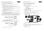
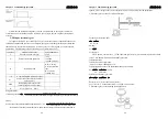
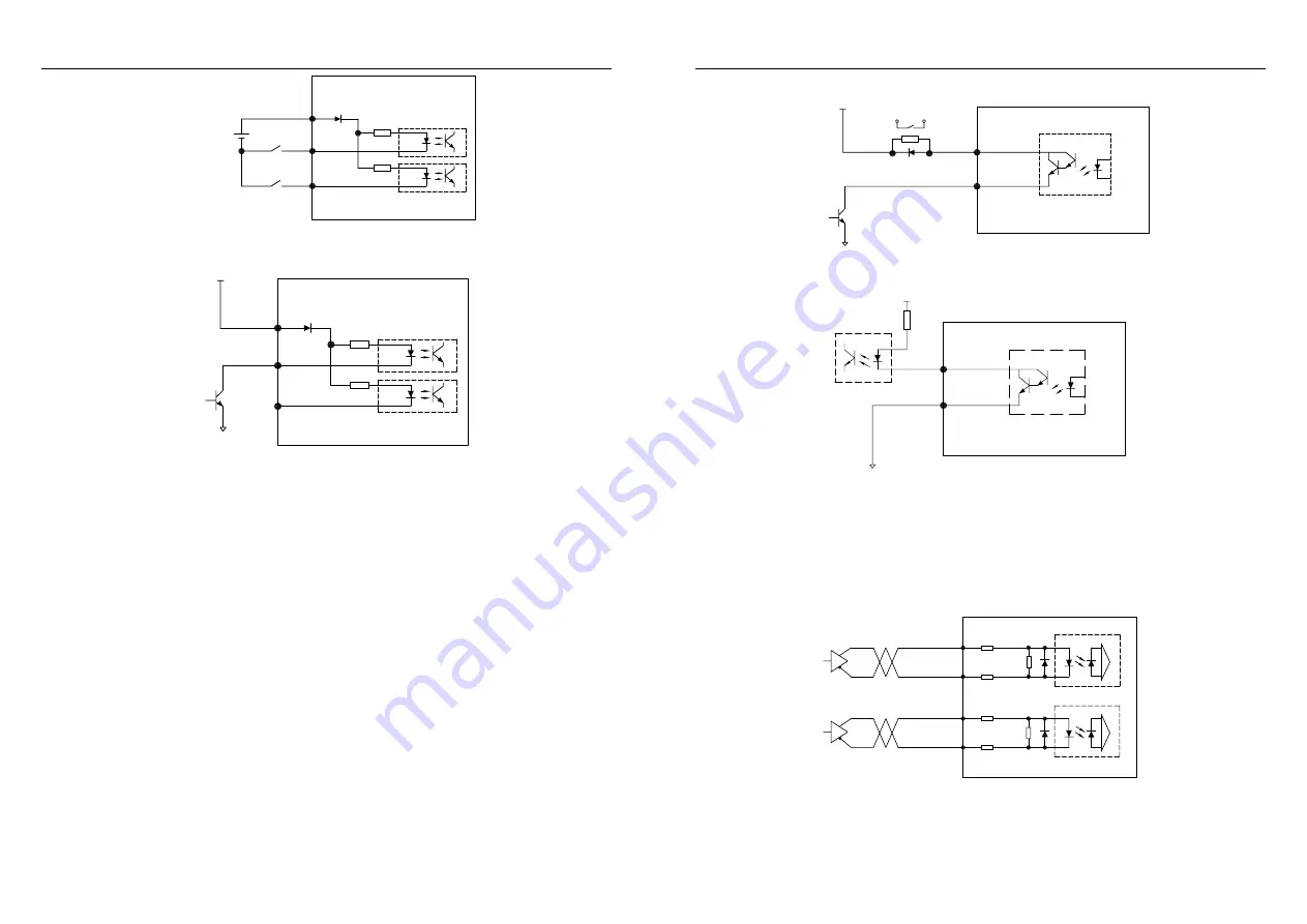
3-4-3 Position pulse instructions
Position pulse instructions (C3)
There are two connection ways of differential drive and single-ended drive, recommend
difference drive method. To wire appropriately use twisted pair.
Drive current 8 to 15 mA
, use
parameters L035 to set to work mode: Pulse and symbol, positive or negative pulse, quadrate pulse.
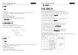
C3-1: Difference drive
110Ω
1KΩ
PULS-
SIGN-
SIGN+
110Ω
PULS+
Servo drive
110Ω
1KΩ
110Ω
★
Maximum pulse frequency 500kHz (kpps)
Not suffer interference, the recommended this method.


