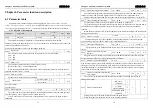

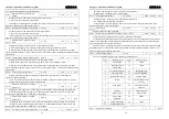

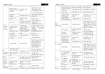


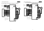

Chapter 7 Alarm
ADSD-S-S
73
Motor wiring U, V,
W phase sequence
mistakes
checking U,V,W
wiring
connecting to U, V, W
wiring properly, and
corresponding with the U,
V, W tag of drives plug
encoder zero
changed
checking encoder zero
reinstalling encoder and
tuning to zero
encoder wiring
error
checking encoder
wiring
wiring properly
blind motor
checking the motor and
mechanical connection
Please contact with
distributors or
manufacturer to solve.
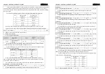
instructions pulse
frequency is too
high
checking input
frequency and pulse
points multiple
frequency parameters
reducing input frequency;
adjusting pulse points
multiple frequency
parameters
position loop gain
is too small
checking parameters
L009
increasing the position
loop gain
Over proof
detection range is
too small
checking parameter
L079
increasing L079
parameter numerical
Err 4
position
out of
tolerance
torque shortage
checking torque
Increasing torque limit and
position instructions
smooth filtering time;
reducing the load;
changing lager power
driver and motor.
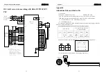
Err 7
driving ban
abnormal
both CCWL and
CWL driving ban
import are invalid
when the servo is
ON
checking the CCWL
and the CWL wiring
Correctly input CCWL
and CWL signal, if do not
use them can set
parameters L097 to shield.
blind motor
checking the motor and
mechanical connection
Please contact with
distributors or
manufacturer to solve
.
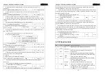
Err 8
position
deviation
counter
overflow
instructions pulse
abnormal
checking instructions
pulse
-
encoder wiring
error
checking the encoder
wiring
wiring properly
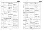
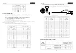
Err 9
encoder
fault signal
encoder cables and
checking the encoder changing encoder cables
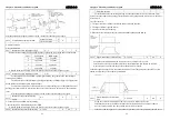
Chapter 7 Alarm
ADSD-S-S
74
connectors
badness
cables and connectors
and connectors
motor model is not
set properly
checking motor model
reinstalling motor model
blind motor
checking
the
encoder
changing
the
encoder
among the motor
wiring U, V, W
shorted circuit
checking U,V,W
wiring
connecting to the U, V, W
wiring properly
motor winding
insulation damage
checking the motor
change the motor
driver damage
checking the driver
during the power is given
again, if the motor has no
problem but the alarm still
happened, the driver may
damage and change it
bad grounding
checking the ground
wiring
wiring properly
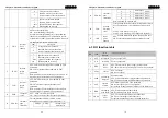
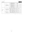
Err 11
power
module fault
suffer the
interference
checking the sources
of interference
increasing line filters,
keeping far from the
sources of interference
among the motor
wiring U, V, W
shorted circuit
checking U,V,W
wiring
connecting to U,V,W
wiring properly
motor winding
insulation damage
checking the motor
change the motor
Err 12
over current
drive damage
checking the drive
during the power is given
again, if the motor has no
problem but the alarm still
happened, the driver may
damage and change it
over the rated load
and continuously
running
checking the brake
load rate
reducing the load or
changing power driver
the
system
is instability
checking the motor
running whether
oscillations
reducing the system gain
accelerated and
deceleration is too
fast
checking the motor
running whether
smooth
increasing accelerated
and deceleration time
Err 13
overload
encoder zero
changed
checking encoder zero
reinstalling encoder and
tuning to zero
Err 14
input ac power is
checking the power
make voltage accord with


