background image

Med Touch Series LCD Alarm Systems

Powerex  

  150 Production Drive  

  Harrison, OH  45030  

  USA

P   1.888.769.7979  

  F   513.367.3125  

  www.powerexinc.com

IN597400AV  

  08/2016

Page 38 of 56

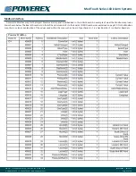
From  the  Main  Page  of  the  RTA  website,  click  on  Modbus  RTU  Master.  An  example  Modmap  of  what  is  displayed  is  shown  below.  The 

Read Scan Lines are generated automatically by the Ethernet/Rabbit board and will match the configuration of the alarm panel. Individual 

informational items may be selected to communicated to the BACnet module for use on the building automation system.

BACnet/IP Server Settings

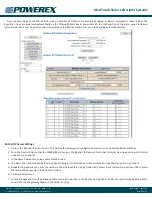
1.  Click on the BACnet/ IP Server button. This will put the gateway into configuration mode so you can edit the BACnet settings.
2.  Enter the Device instance that the 460MMBS will have on the BACnet/ IP Network. Note that this must be unique amongst all BACnet 

devices on the network.

3.  In the Name field enter a unique name for the device.
4.  The Description and Location fields are optional. Filling in this information is recommended to identify the device on a network.
5.  Beneath the Read Groups, verify the number of Analog Input (AI), Analog Outlet (AO), Binary Input (BI) and Binary Output (BO) objects 

that you will be exposing to the BACnet/ IP Client.

6.  Click Save Parameters.
7.  To save changes and force the gateway back to running mode, click on the Reboot Now button and after 5 seconds hit the Refresh button. 

You should see the gateway appear in the Mode: Running.

Summary of Contents for Med Touch Series

Page 1: ...to 4 transducer sensor inputs 2 85 LCD touch screen displays normal and high low alarm conditions for one 4 20 mA sensor input The LCD touch screen allows all alarm programming and set up to be done...

Page 2: ...error message will be displayed if incorrect sensor or no sensor is attached Shall be capable of displaying gas readouts PSI kPa BAR inHg or mmHg Gas alarm repeat feature is factory set at 10 minutes...

Page 3: ...sing the Alarm Program Mode 18 Programming High Low Alarm Pressure Set Points 19 Programming Remote Signal Master Points NO or Disable 19 Programming Remote Signal Master Points NFPA Labels 19 Program...

Page 4: ...rminal strip for electrical wiring An isolated transformer reduces the 110V or 220V AC input to low voltage DC Front Panel The front panel includes enclosed printed circuit boards with programming cir...

Page 5: ...the ceiling and eliminates contamination issues such as having to set up a tent in order to remove ceiling tiles Risers DISS x O D tube gas specific risers with our Frontall front loaded check valve a...

Page 6: ...e contractor is to provide rigid mounting that will support the alarm box on both sides The metal flanges provided on both sides of the rough in box are to rest against the rigid mounting brackets Scr...

Page 7: ...sure the drop is for the proper gas service Using a purge gas to insure cleanliness in the tubes silver braze the joints Do not use soft solder Conduct heat away from the check valves Per NFPA 99 Chap...

Page 8: ...etached from the front panel simply snap it back on Attach the two left right side lanyard cables to the alarm back box and if necessary front panel using the screws provided Wiring the Alarm Front Pa...

Page 9: ...in Appendix F The transducers have been designed so that they may be installed in a standard 4 x 4 x 2 1 8 electrical junction box for added protection A panel mount feature has been provided to allow...

Page 10: ...on Visually verify that the appropriate transducer wire pair has been attached to the appropriate gas module by looking at the front of the alarm panel If there is not an Error Condition and a System...

Page 11: ...oints two connection points for each transducer sensor The pairs are labeled 1 IN thru 4 IN on the circuit board The white wire from the transducer should be landed in the WHT position and the black w...

Page 12: ...Land the 4 20mA signal wire in the Number 2 terminal port Land the ground wire to the Number 3 terminal port For 4 20mA transmitters with loop power supplied by the Alarm Circuit Board 35 0037 Land t...

Page 13: ...it feeding this alarm panel The toggle switch on the front of the power supply should be placed in the ON position Check the green power LED indicator on the front of the button module It should be il...

Page 14: ...gnal Transducer Modules The High and or Low Pressure indication will be displayed along with the actual highest or lowest pressure which occurred Remote Signal Master Module If there was an alarm cond...

Page 15: ...the pressure text box NOTE Alarm settings are maintained even if power is interrupted Units of Measure The Units of Measure is displayed as PSI inHg BAR or kPa whichever is selected during programmin...

Page 16: ...humidity etc Master dry contact modules will provide up to 8 alarm signals when used in communication with dry contact sensors For each signal point a label must be selected from a pre loaded databas...

Page 17: ...ces of the medical gas distribution system in communication with the remote equipment dry contacts connected to it and provide the emergency instructions programmed by the user The remote signals mast...

Page 18: ...d NOTE Only authorized personnel should program the alarm It is important to note that while the panel being programmed is in the program mode it is not monitoring the medical gas system and alarm con...

Page 19: ...o that the high and low set points must be at least 1 psig in Hg 1 bar or 1 kPa increments apart The high set point will not be able to be set below the low set point and vice versa Re Programming the...

Page 20: ...acing the board in the program mode and touching the CAL function icon the calibration input screen shown here is displayed The alarm panel has been calibrated and programmed and does not ever require...

Page 21: ...iew of all of the programming for the circuit board It does not provide any programming options It is simply a view only screen The first line provides the software version The Cal value represents an...

Page 22: ...how it appears as displayed as part of the gas or transducer master display When an alarm occurs the emergency instructions will appear alternately with the normal information labe NOTE The text will...

Page 23: ...the numeric value that a 20mA signal will represent i e 2000 gallons These values will represent the span of the 4 20mA device The HIGH and LOW icons are used to set the respective numeric values tha...

Page 24: ...7 or newer 1 Configure Router Port The port on the router that the Ethernet cable from the Rabbit board will be plugged into must be configured for half duplex Most routers will auto set for this how...

Page 25: ...werexinc com IN597400AV 08 2016 Page 25 of 56 Create Receive Connector SMTP Simple Mail Transfer Protocol is one of the most common ways of sending e mail SMTP is a simple text conversation across a T...

Page 26: ...Med Touch Series LCD Alarm Systems Powerex 150 Production Drive Harrison OH 45030 USA P 1 888 769 7979 F 513 367 3125 www powerexinc com IN597400AV 08 2016 Page 26 of 56...

Page 27: ...ity to bring the laptop close to the alarm panel You will also need a 35 3033 rabbit board programming kit NOTE If your operating system doesn t pull in the driver for the 35 5069 cable you must downl...

Page 28: ...N597400AV 08 2016 Page 28 of 56 Launch the Real Term Serial Capture Program The set up screen should look like this Under the Display Tab check the Half Duplex Box Under the Port Tab 1 Select a baud r...

Page 29: ...abbit board or after if a battery was replaced on the rabbit board when the alarm panel was not under 120 VAC power PPN program panel name this command programs the name of the alarm panel as it will...

Page 30: ...blishes the mail server IP address PUN program user name this command establishes the SMTP user name In the example below we have used powerex wolfcreekmicro com PUP program user password this command...

Page 31: ...r with the internet the Program Gateway must be used PGW program gateway this command establishes communication from the alarm rabbit board through the facilities network server to the internet Below...

Page 32: ...ill set the Modbus ID to 1 PDT PROGRAM DATE TIME Usage PDT0129160842 will set RTC to Jan 29th 2016 at 8 42am PDT0203162042 will set rtc to Feb 3rd 2016 at 8 42pm PIP PROGRAM IP Usage PIP192 168 0 50 w...

Page 33: ...cess Web access to the overview and alarm log pages can be done in several ways Viewing the Website of the Alarms Panels from within your facility ONLY Add the IP address of each rabbit board to your...

Page 34: ...icking on the Alarm Log button on the left side of the website see above This event log will display up to 100 recent events with the most recent event on the top line and the oldest event on the bott...

Page 35: ...the plug labeled BLACK Refer to the wiring diagram on the page 55 for proper connections The RS485 data wires blue white and black have been pre wired to the input plug of the 460MMBS gateway Connect...

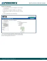
Page 36: ...n Page click on Port Configuration It should appear as shown below 2 Enable port 0 and set Mode to RS485 2 wire Half Duplex 3 Set Serial Baud to 9600 Parity None Data Bits 8 and Stop Bits 1 4 Click Sa...

Page 37: ...map for the largest Powerex alarm panel is embedded in the rabbit board An example of what the Modbus map looks like is shown below The Board ID numbers in the left hand column refer to the boards COM...

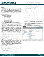
Page 38: ...his will put the gateway into configuration mode so you can edit the BACnet settings 2 Enter the Device instance that the 460MMBS will have on the BACnet IP Network Note that this must be unique among...

Page 39: ...mmHg 019 PSI or 1 mmHg 039 inHg NFPA National Fire Protection Association The National Fire Protection Association is an association engaged in standards development NO Normally Open An electrical ci...

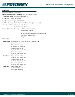
Page 40: ...maximum 240 V Pressure Measurement Accuracy 0 30 inHg transducer 1 Vacuum Gas Evacuation 0 100 PSIG transducer 1 Oxygen Nitrous Oxide Medical Air Carbon Dioxide 0 250PSIG transducer 1 Nitrogen Dimens...

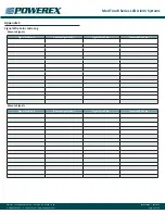
Page 41: ...88 769 7979 F 513 367 3125 www powerexinc com IN597400AV 08 2016 Page 41 of 56 Appendix C Signal Wire Color Code Log Remote Signals Signal Position Remote Signal Label Signal Wire Color Common Wire Co...

Page 42: ...D Master Alarm Signals The master alarm signals which are pre loaded in the database see page 19 will appear in the sequence below starting at the top of the first column to the bottom of the first c...

Page 43: ...es LCD Alarm Systems Powerex 150 Production Drive Harrison OH 45030 USA P 1 888 769 7979 F 513 367 3125 www powerexinc com IN597400AV 08 2016 Page 43 of 56 Appendix E Digital Alarm or Master Alarm Wir...

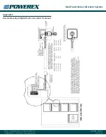
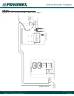
Page 44: ...D Alarm Systems Powerex 150 Production Drive Harrison OH 45030 USA P 1 888 769 7979 F 513 367 3125 www powerexinc com IN597400AV 08 2016 Page 44 of 56 Appendix F Remote Mounting of Digital Touch Scree...

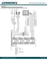
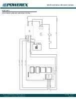
Page 45: ...Systems Powerex 150 Production Drive Harrison OH 45030 USA P 1 888 769 7979 F 513 367 3125 www powerexinc com IN597400AV 08 2016 Page 45 of 56 Appendix G Wiring Schematic Equipment Wiring to Digital...

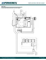
Page 46: ...larm Systems Powerex 150 Production Drive Harrison OH 45030 USA P 1 888 769 7979 F 513 367 3125 www powerexinc com IN597400AV 08 2016 Page 46 of 56 Appendix H Remote Mounting of Digital Touch Screen M...

Page 47: ...Alarm Systems Powerex 150 Production Drive Harrison OH 45030 USA P 1 888 769 7979 F 513 367 3125 www powerexinc com IN597400AV 08 2016 Page 47 of 56 Appendix I Equipment wiring to Digital Touch Screen...

Page 48: ...rm Systems Powerex 150 Production Drive Harrison OH 45030 USA P 1 888 769 7979 F 513 367 3125 www powerexinc com IN597400AV 08 2016 Page 48 of 56 Appendix J Digital Touch Screen Alarm Ethernet Ribbon...

Page 49: ...s LCD Alarm Systems Powerex 150 Production Drive Harrison OH 45030 USA P 1 888 769 7979 F 513 367 3125 www powerexinc com IN597400AV 08 2016 Page 49 of 56 Appendix K Electrical Wiring Schematic with B...

Page 50: ...LCD Alarm Systems Powerex 150 Production Drive Harrison OH 45030 USA P 1 888 769 7979 F 513 367 3125 www powerexinc com IN597400AV 08 2016 Page 50 of 56 Appendix L Ethernet Ribbon Cable and BACnet Co...

Page 51: ...D Alarm Systems Powerex 150 Production Drive Harrison OH 45030 USA P 1 888 769 7979 F 513 367 3125 www powerexinc com IN597400AV 08 2016 Page 51 of 56 Appendix M Text Message Carriers char Carriers SM...

Page 52: ...Med Touch Series LCD Alarm Systems Powerex 150 Production Drive Harrison OH 45030 USA P 1 888 769 7979 F 513 367 3125 www powerexinc com IN597400AV 08 2016 Page 52 of 56...

Page 53: ...Med Touch Series LCD Alarm Systems Powerex 150 Production Drive Harrison OH 45030 USA P 1 888 769 7979 F 513 367 3125 www powerexinc com IN597400AV 08 2016 Page 53 of 56...

Page 54: ...Program IP PGW Program Gateway IP PMI Program SMTP Mail Server IP PUN Program User Name PUP Program User Password PCX Program Contacts for Alarm Panel 1 2 3 4 5 Common Commands PPN Program Panel Name...

Page 55: ...taxes duties licenses or other fees imposed by any governmental authority upon the production sale shipment and or use of Products covered hereunder The warranties and remedies herein are the sole and...

Page 56: ...d or use of Products for certain purposes which may vary from those in neighboring areas While Powerex attempts to assure that its Products comply with such codes it cannot guarantee compliance and ca...

Reviews: