Med Touch Series LCD Alarm Systems
Powerex
•
150 Production Drive
•
Harrison, OH 45030
•
USA
P 1.888.769.7979
•
F 513.367.3125
•
www.powerexinc.com
IN597400AV
•
08/2016
Page 20 of 56
Programming the Repeater Delay
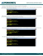
After placing the board in the program mode and touching the
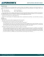
Repeat function icon, the remote signal input screen (shown here)
is displayed. The current repeater delay programmed is displayed in
the white box at the top. In the example
shown here, Rp 10 means the repeater
delay is programmed for 10 minutes.
Entering zero will disable the repeater.
Use the keypad to type in the number
of minutes you would like (maximum is
240),
• then touch Enter
• on the next screen touch Back
• on the next screen touch Save
Programming the Units of Measure
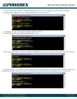
After placing the board in the program
mode and touching the Units function
icon, the units input screen (shown
here) is displayed. The alarm panel has
been pre-programmed with the units
desired based on the part number
which was ordered. The positive gas
service options are; PSI, kPa and BAR.
The negative gas service options are;
inHg and mmHg. Simply
• touch the button you would like to
re-program the units
• then touch Enter
• on the next screen touch Back
• on the next screen touch Save
Adjusting the Digital Pressure Calibration
The digital line pressure may be
adjusted slightly (per the chart below)
by following the simple procedure
below.
This can be done by one person
at the alarm panel – no need to open/
adjust the transducers!
Range of adjustment:
VAC or EVAC /WAGD ± 1 inHg
100 psig transducers ± 3 PSI
250 psig transducers ± 5 PSI
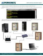
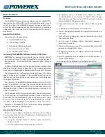
After placing the board in the program
mode and touching the CAL function icon, the calibration input screen
(shown here) is displayed. The alarm panel has been calibrated and
programmed and does not ever require recalibration. If you wish to
slightly change the calibration (usually to match another alarm panel
in immediate area) you may. The number displayed in the white box
at the top of the display is the current pressure reading. Simply
• touch the Down or the Up button until you achieve the pressure
reading desired
• touch OK
• on the next screen touch Back
• on the next screen touch Save
Programming the Board Com ID
NOTE:
This feature is used when the alarm is used in conjunction
with the optional Ethernet module or as a component in a wireless
master panel.
NOTE:
When used in conjunction with the Ethernet module, each
circuit board must have a sequential Identification Number from 1
to 16 based on its position in the alarm panel. 1 thru 4 would be
from the top of the second slot to the bottom of the second slot.
5 – 8 would be from the top of the third slot to the bottom of the
third slot, etc.
NOTE:
When used as a component in a wireless master. Each
8 remote signal dry contact circuit board must have a UNIQUE
sequential Identification Number from 1 to 8 based on its position
in the alarm panel. For additional information see the Powerex
Wireless Master Alarm literature.
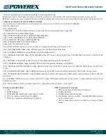
After placing the board in the program
mode and touching the COMID function
icon, the remote signal input screen
(shown here) is displayed. The current
Com ID # programmed is displayed in
the white box at the top. Entering zero
will disable the Com ID for this board.
Use the keypad to;
• type in the Com ID number you
would like
• then touch Enter
• on the next screen touch Back
• on the next screen touch Save.


