Med Touch Series LCD Alarm Systems
Powerex
•
150 Production Drive
•
Harrison, OH 45030
•
USA
P 1.888.769.7979
•
F 513.367.3125
•
www.powerexinc.com
IN597400AV
•
08/2016
Page 19 of 56
Programming the High & Low Alarm Pressure Set Points
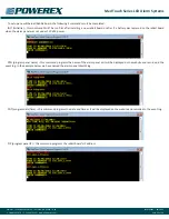
After placing the board in the program mode and touching the
High function icon, the high line pressure set point and programming
keypad is displayed. The currently programmed high pressure alarm
set point is displayed in the white box
in the top left corner. If the gas module
being programmed is a typical 50 psig
delivery pressure gas, the board has
been pre-programmed at the factory
with the high line pressure set point at
60 psig, so the display should show the
number 60. If you wish to change this
setting, simply
• type in the new pressure
• touch Enter,
• on the next screen touch Back
• on the next screen touch Save to adjust the pressure setting.
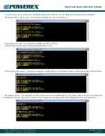
After placing the board in the program
mode and touching the Low function
icon, the low line pressure set point and
programming keypad is displayed. The
currently programmed low pressure
alarm set point is displayed in the white
box in the top left corner. If the gas
module being programmed is a typical
50 psig delivery pressure gas, the board
has been pre-programmed at the factory
with the low line pressure set point at
40 psig, so the display should show the
number 40. If you wish to change this
setting, simply
• type in the new pressure
• touch Enter
• on the next screen touch Back
• on the next screen touch Save to adjust the pressure setting.
NOTE:
The alarm is designed with a safety feature so that the high
and low set points must be at least 1 (psig / in Hg), 1 (bar) or 1
(kPa) increments apart. The high set point will not be able to be set
below the low set point and vice versa.
Re-Programming the Remote Signal (Master) Alarm Points
(NO or Disable)
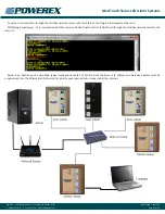
After placing the board in the program mode and touching the Input
function icon, the remote signal input screen (shown here) is displayed.
The input number displayed on the top
line of the white box corresponds to
the signal being programmed. You may
toggle to the next or previous signal
by using the double arrow buttons in
the bottom row. The master boards are
pre-programmed with all signal points
programmed NC (normally closed) in
compliance with NFPA 99. You may re-
program each individual signal as NO
(normally open) or you may Disable
each individual signal point by touching
the NO or Disable button. You may re-
program all of the signal points (up to 8) before
• touching the OK button
• on the next screen touch Back
• on the next screen touch Save.
Programming the Remote Signal (Master) Alarm Points –
NFPA Alarm Menu
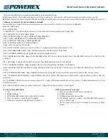
After placing the board in the program mode and touching the Text
function icon (see left display above), the remote signal input screen
(right above) is displayed. The input number displayed on the top of
the second white box corresponds to the signal being programmed.
You may toggle to the next or previous signal by using the Down or
Up buttons. When you are on the label number that you wish to
program, use the double arrow buttons in the bottom row to toggle
thru the database of NFPA 99 master alarm signals. The sequence of
the master alarm signals is per Appendix D. You may program all of
the signal points (up to 8) before
• touching the OK button
• on the next screen touch Back
• on the next screen touch Save.


