


Med Touch Series LCD Alarm Systems
Powerex
•
150 Production Drive
•
Harrison, OH 45030
•
USA
P 1.888.769.7979
•
F 513.367.3125
•
www.powerexinc.com
IN597400AV
•
08/2016
Page 35 of 56
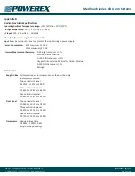
BACnet Interface
Overview
The 460MMBS Gateway device seamlessly connects Modbus RTU
Slave devices to a BACnet/IP client. By following this guide, you will
be able to configure the 460MMBS Gateway for basic operation. You
will set the devices network settings and parameters to the proper
configuration for initial operation and physically place the device in
the network.
Required Tools & Data
You will need the following tools:
•
The 460MMBS Gateway
•
The provided CD-ROM
•
A Working PC (Windows based)
•
An Ethernet Crossover Cable
•
A 12-24 VDC power source
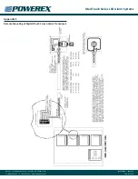
Connecting the 460MMBS Gateway device to the Alarm:
CAUTION:
The Gateway device should only be installed after all
wall construction and finishing is completed to prevent ingress of
dust and debris. This contamination can adversely affect its proper
function.
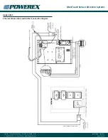
An Ethernet/Rabbit board should have already been installed in the
back box and programmed as described in the previous pages. See
the section on Integrating the Ethernet/Rabbit boards into a network.
The Gateway device configuration should be done at the Alarm
panel. The device can be clipped to the provided bracket in the top
right hand corner of the back box or be loose near the PC being used
to configure the device.
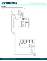
The power for the 460MMBS Gateway device will come from the
Orange (+) and Black (-) wires in the Alarm back box. Connect the
orange wire to the plug labeled RED (+) and the black wire to the
plug labeled BLACK (-). Refer to the wiring diagram on the page 55 for
proper connections.
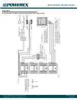
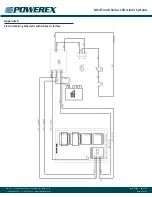
The RS485 data wires, blue, white and black, have been pre-wired
to the input plug of the 460MMBS gateway. Connect the ends of
these wires the “MODBUS/RS485” plug on the rabbit board, White
wire to the “A” port, Blue wire to the “B” port and Black wire to “GRD”
port. Refer to the wiring diagram on page 50 for proper connections.
Always turn the power off to the alarm panel before making any
electrical connections or disconnections.
Accessing the Main Page
Before you can configure the gateway itself, you must configure
the network settings to connect the gateway. The following steps will
connect the gateway properly.
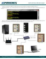
1. Using the provided Ethernet crossover cable, connect the
device to the PC.
2. Turn the power ON to the Alarm Panel and the PC.
3. The gateway device is shipped with a default IP Address
of 192.168.0.100 and a Subnet of 225.255.255.0. Change
the IP Address and Subnet of your PC, if necessary, to allow
communication to the gateway device.
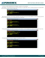
4. Open a Web browser and enter the device IP Address in the
URL.
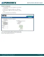
5. The Main page should appear as shown below.
6. Click on Configuration Mode in the upper left-hand corner of
the screen.
7. Next to Device Configuration. Click the Edit button to modify
the Network Settings.
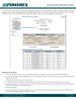
8. Enter the new IP Address, Subnet, and Default Gateway to
work in your network.
9. Click Save Parameters to save the network setting. Restart the
gateway by clicking Restart Now.
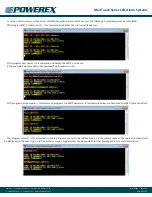
10. Change your PC back to its original IP and Subnet setting for
your network.
11. Enter the gateway’s new IP Address in the Web browser to
launch the Main Page.
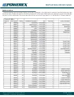
12. Continue with the Gateway Port Configuration section.
NOTE:
Browser configuration is compatible with Chrome, Internet
Explorer, and Firefox.