4. Front panel operation
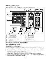
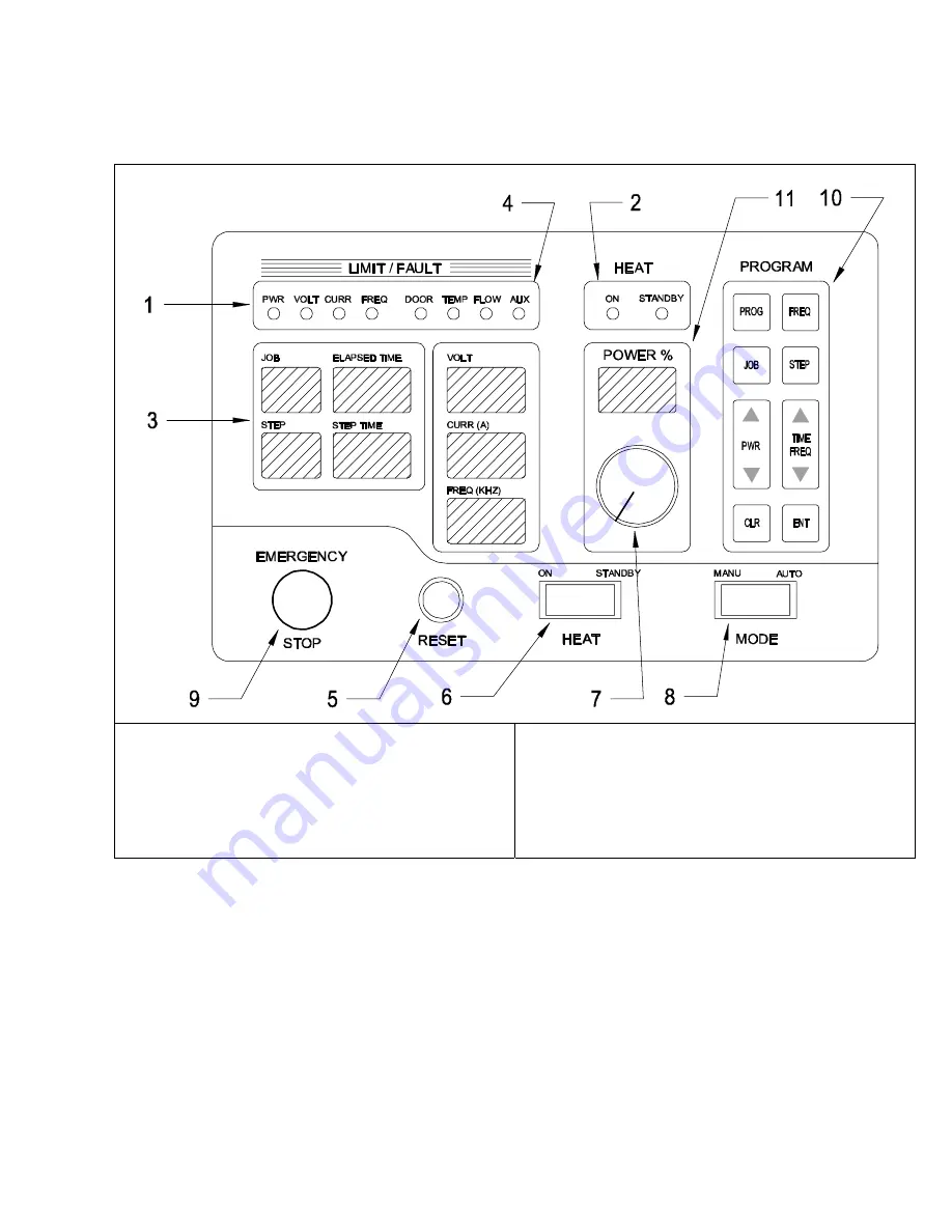
This section identifies and describes the various parts of the front panel.
1)
Limit and trip LED
2)
Heat On/Off LEDs
3) Program
Indicators
4)
Volt, Curr and Freq Indicators
5) Reset
button
6) Heat
switch
7) Power
Knob
8) Mode
Switch
9) E-Stop
Switch
10) Program
Buttons
11) Power
Indicator
Figure 2: Front panel layout for model 3-135/400-3.
4.1. Limit and trip indicators.
Identified by
1
in Figure 2 on page 9.
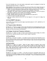
Limit indicators:
These indicators are yellow in color and are lit when the heat station is not
properly tuned. The power output of the unit is limited below the desired level set by the power
knob or remote pendant. There are four limit indicators:
•
POWER: If lit the power is being limited at 3kW.
•
VOLT: If lit the capacitor voltage is being limited at 350V rms.
•
FREQ: If lit the circuit is being limited at the resonant frequency of the resonant tank.
•
CURRENT: If lit the inverter current is being limited at 70A peak. (Note: The load coil
current could be much higher than 70A peak).
9


